
electronic engine control (EEC)
Provides information about Ford's Electronic Engine Control Systems, including EEC-III, EEV-IV, & EEC-V.
Section 28 of Ford's 1984 EEC-III Tester Manual covering the 5.0L engines with central fuel injection (CFI).
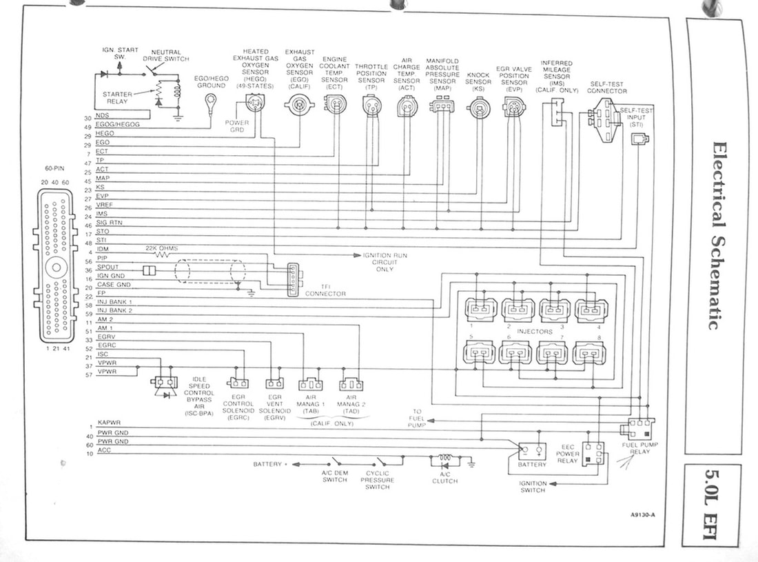
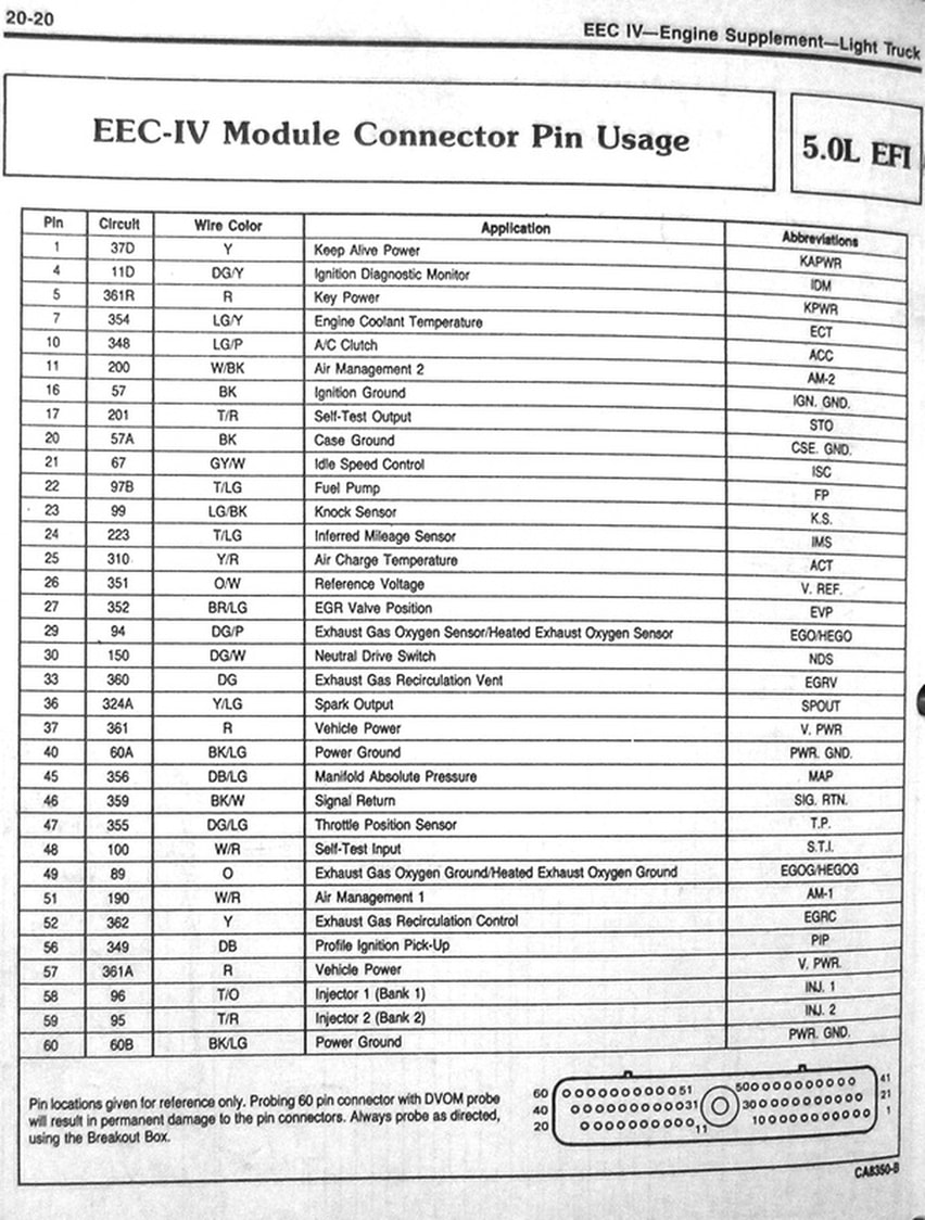
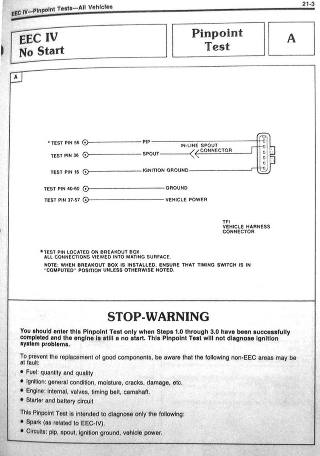
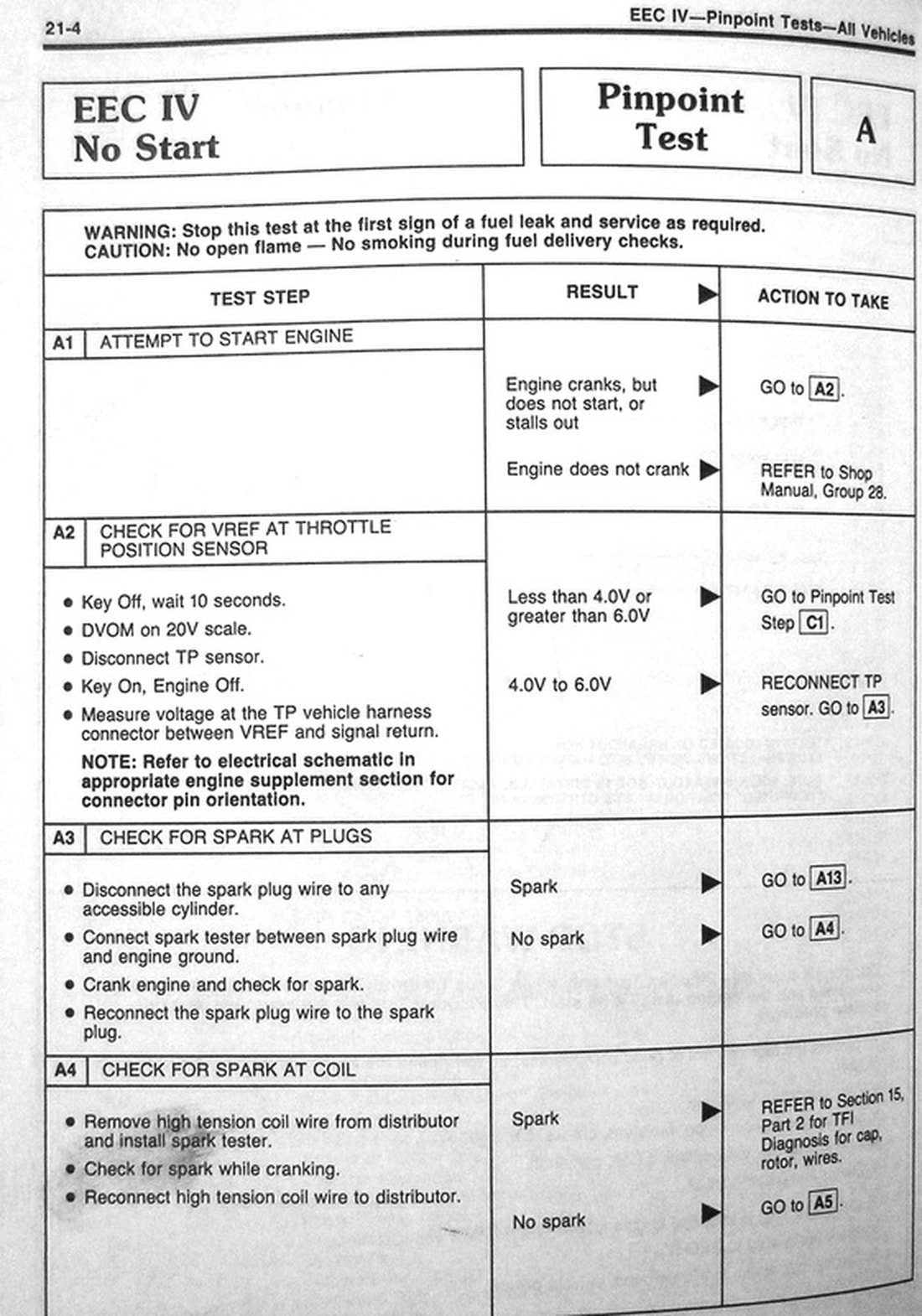
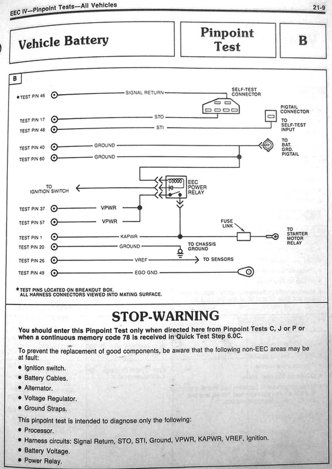
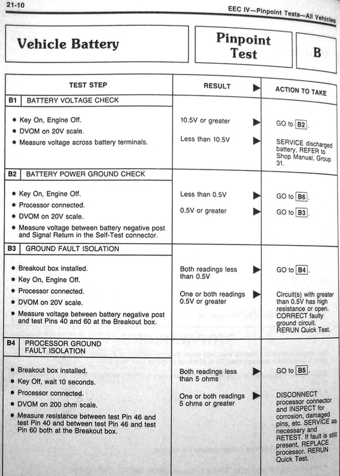
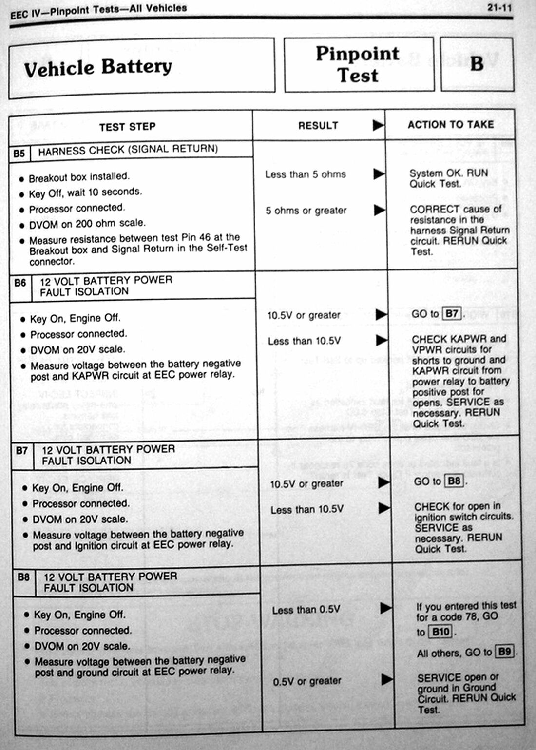
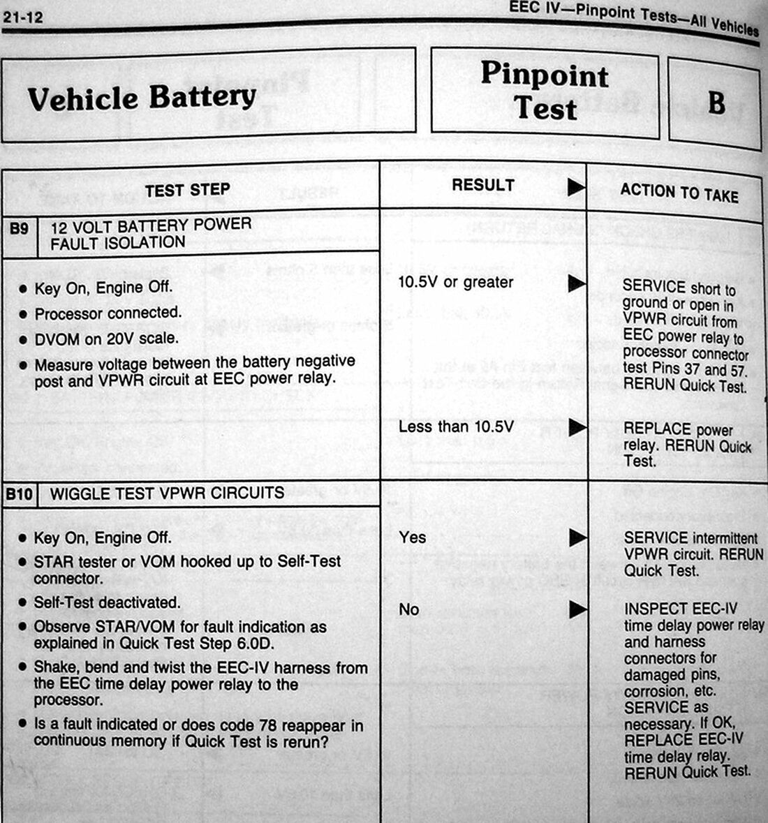
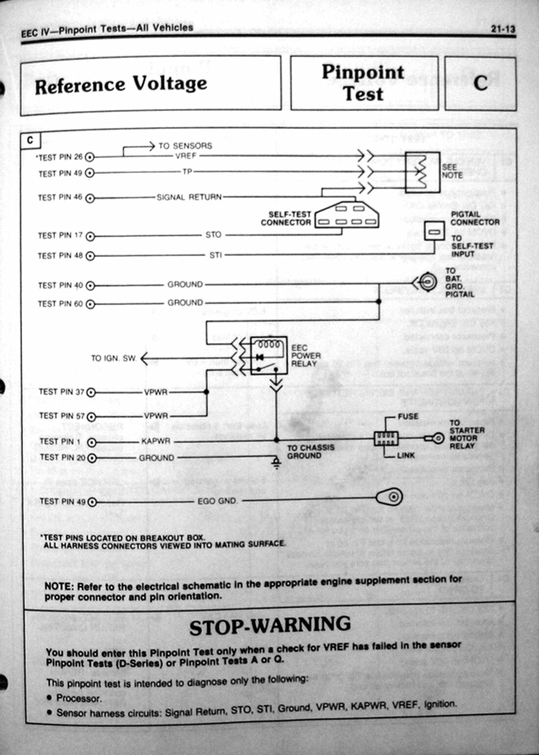
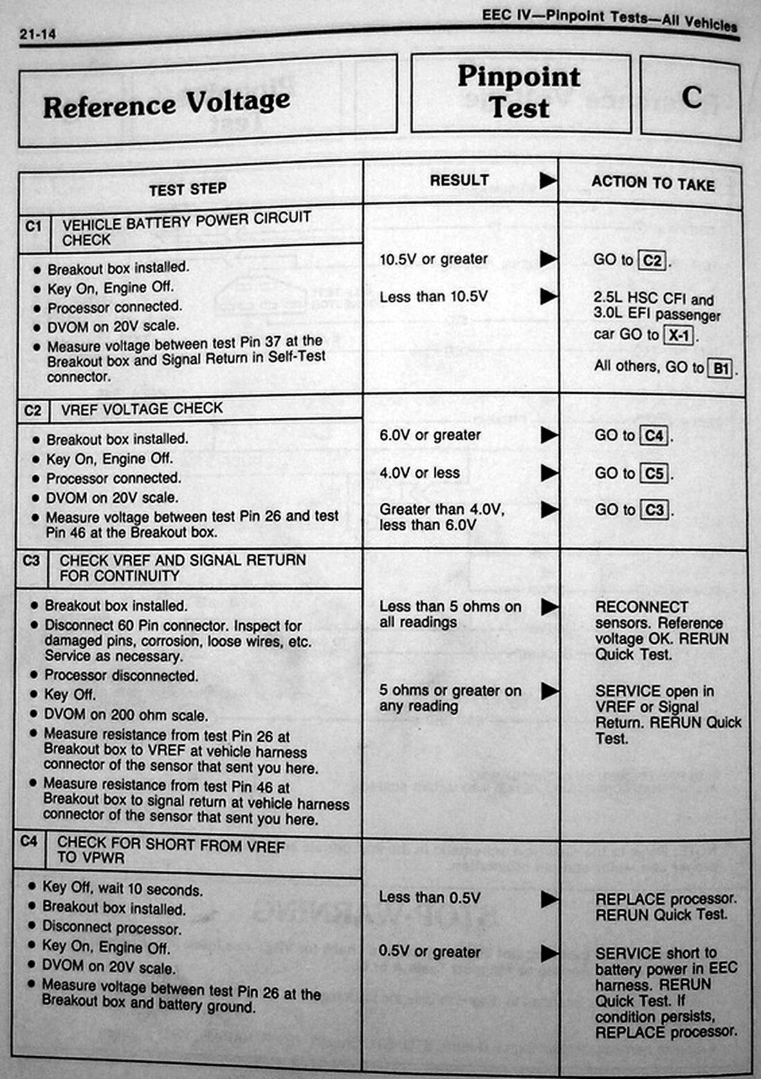
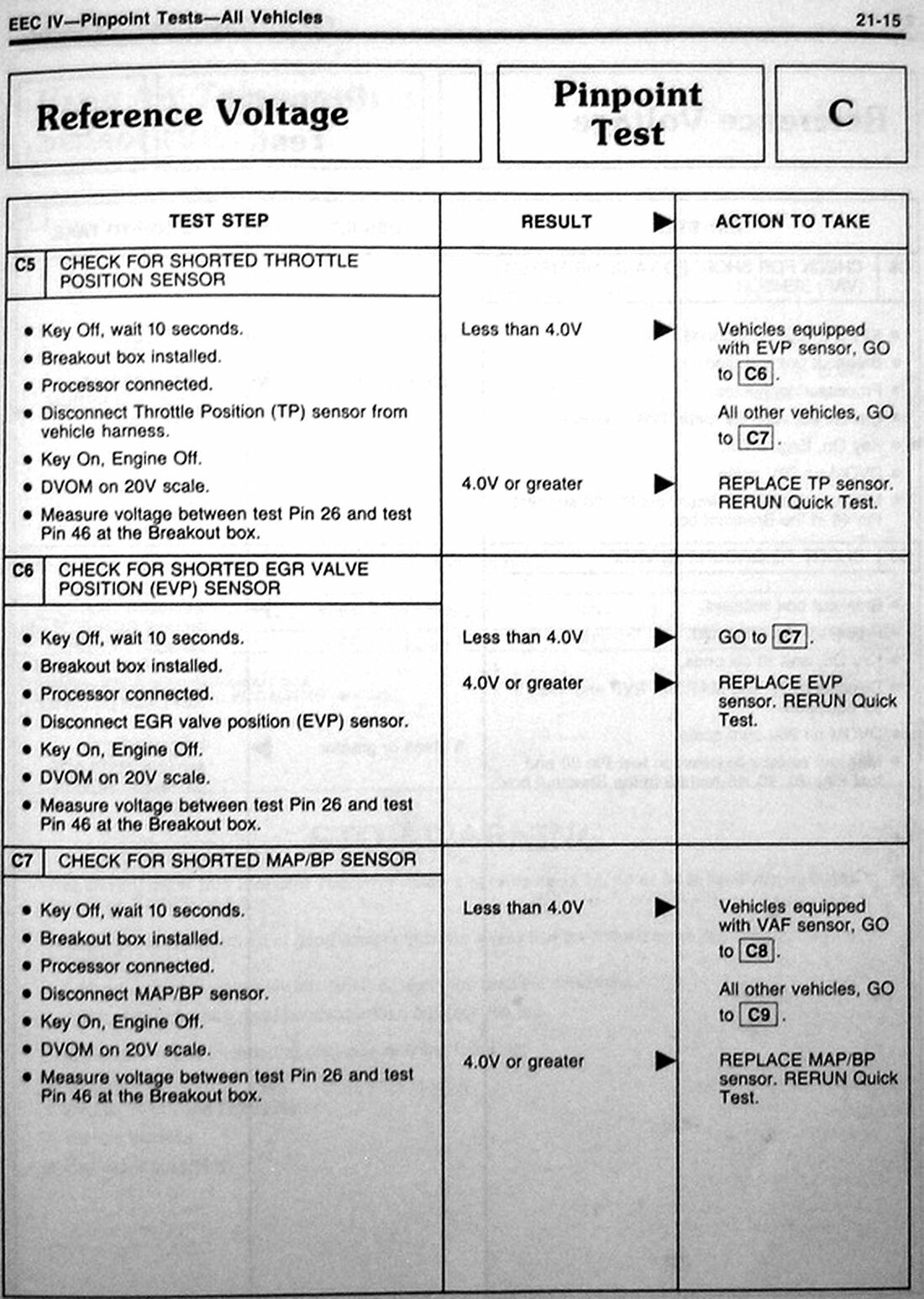
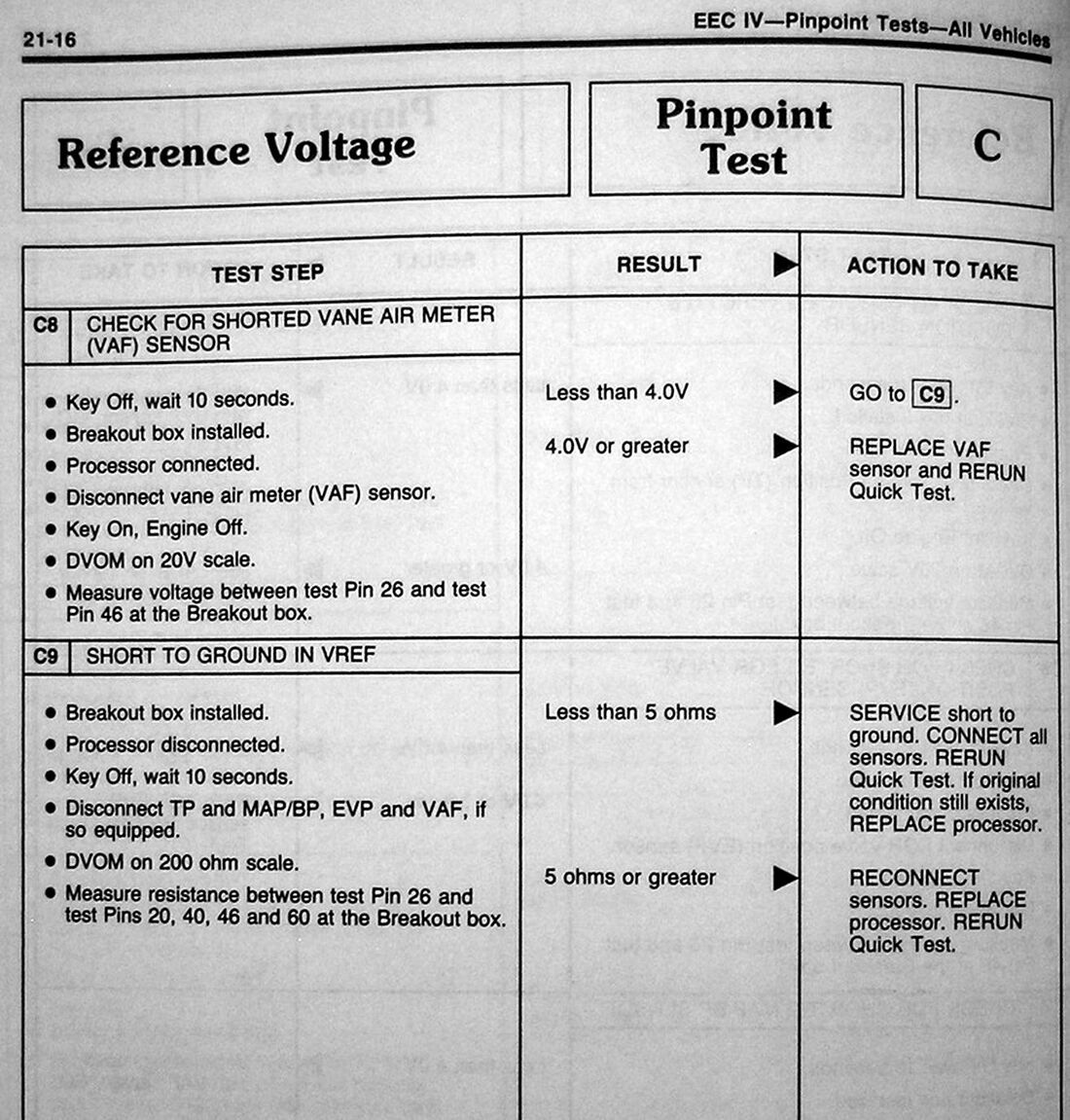
Schematics, connector pin-outs, and test procedures for Ford's EEC-IV systems.
The EEC-IV equipped engines use an older diagnostic system to monitor and report engine related malfunctions. This system is known as On Board Diagnostics (OBD-I). The Diagnostic Trouble Codes (DTC's) are two or three digit numbers and can be read through the use of a scan tool, an analog voltmeter, or with the Malfunction Indicator Light (MIL) [Check Engine or Service Engine Soon light]. Use one of the following methods to obtain the DTC's and then refer to the 2-Digit Code tab.
Scan Tool Method
Scan Tool Method
- Connect the scan tool to the self-test connectors. Make certain the test button is unlatched or up.
- Start the engine and run it until normal operating temperature is reached.
- Turn the engine OFF and wait 10 seconds.
- Activate the test button on the STAR tester.
- Turn the ignition switch ON but don't start the engine.The codes will be transmitted. Six to nine seconds after the last code, a single separator pulse will be transmitted. Six to nine seconds after this pulse, the codes from the Continuous Memory will be transmitted.
- Record all service codes displayed. Do not depress the throttle during the test.
- After the test, compare the DTC's retrieved from those in the 2-digit or 3-digit charts.
|
Analog Voltmeter or Test Light Method
If you have an analog volt meter, meaning one with an actual dial with a pointer, set the voltmeter to read DC 0-15 volts. Then connect the positive lead of the meter to the battery positive terminal and connect the negative lead to the Self-Test Output (STO) pin of the diagnostic connector. If you don't have an analog volt meter you can get the same results by replacing the volt meter with a simple 12v bulb. Then, follow the directions given previously in the scan tool procedure. To activate the procedure, use a jumper wire to connect the signal return pin on the diagnostic connector to the self test input connector. The self test input line is the seperate wire and connector wih or near the diagnostic connector. The codes will be transmitted as groups of needle sweeps. This method may be used to read either 2 or 3 digit codes. The Continuous Memory codes are seperated by the other codes by 6-seconds, a single sweep, and then another 6-second delay. Compare the 2-digit Diagnostic Trouble Codes with those on that tab. |
|
Malfunction Indicator Lamp (MIL) Method
The Malfunction Indicator Lamp (MIL) on the dash (Engine Light) can be used to retrieve the stored codes. This method does not allow for any system investigation. This should only be used in the field where quick checks are needed. Follow the directions previously given for the scan tool procedure. To activate the tests, use a jumper wire to connect the signal return pin on the diagnostic connector to the Self-Test Input (STO) connector. The self test input line is the separate wire and connector with or near the diagnostic connector. Codes are transmitted with a pause between flashes. Code 32 would be sent as 3-flashes, a pause and then 2-flashes. A slightly longer pause separates the codes. The only way to repeat the code is to recycle the system. The Continuous Memory Codes are separated from the other codes by 6-seconds, a flash and then another 6-second delay. Compare the 2-digit and 3-digit Diagnostic Codes with the appropriate chart.
Memory Codes
Memory codes are problems that the computer has noticed in the past. If for example there was a loose wire to a solenoid that only lost contact while driving but was making contact while testing the system there would be NO HARD FAULT CODE. The code would show up IN MEMORY. The same would happen for a sensor that only went out of range occasionally. Memory codes come out AFTER the separator pulse.
NOTE: The computer will erase the memory after a certain number of engine re-starts if the problem does not repeat itself. The number of re-starts varies from 20 to 80 depending on the year of the vehicle. The later models keep memory longer.
Key On Engine Running (KOER) Test
1. Make sure engine is fully warmed. If in doubt, run engine at 2000 rpm for 2 minutes.
2. Turn ignition off and wait 10 seconds for system to shut off. Make sure A/C is off and transmission is in Park (automatic) or Neutral (manual).
3. Hook up light and jumper (or tester if you have one).
4. Make sure vehicle is safe to run and start engine.
5. Engine I.D. should be output.
6. Step on brake and turn steering wheel 1/4 turn. If the vehicle has an overdrive cancel switch, push it.
7. If a "Goose" pulse is received, move throttle quickly 1/2 way down and release.
8. Fast Codes are output (ignore).
9. Read codes.
10. See code explanations and check components as necessary. Use FIRST CODE OUTPUT and retest after any repairs are made.
Key On Engine Off (KOEO) Test
NOTE: On 4.9L trucks with a manual transmission hold the clutch pedal in during this test. On Diesel engine trucks hold the throttle to the floor during this test.
1. Make sure engine is fully warmed. If in doubt, run engine at 2000 rpm for 2 minutes.
2. Turn ignition off and wait 10 seconds for system to shut off. Make sure A/C is off and transmission is in Park (automatic) or Neutral (manual).
3. Hook up light and jumper (or a tester if you have one). Turn key to ON (do not start engine).
4. Fast Codes are output (ignore fast light flashes).
NOTE: Unhook self test input jumper (or tester if used) at any time during code output to erase memory.
5. Read hard faults.
6. Separator Pulse.
7. Read memory codes.
8. See code explanations and check components as necessary.
Use FIRST CODE OUTPUT and retest after any repairs are made.
Test Hook-Ups
Clearing Codes
These codes are kept in memory for 40 warm up cycles. To clear the codes for purposes of testing or confirming repair, perform the code reading procedure. When the fault codes begin to be displayed, de-activate the test by either disconnecting the jumper wire or releasing the test button on the hand scanner. Stopping the test during code transmission will erase the continuous memory. Do not disconnect the negative battery cable to clear the codes; the keep alive memory will be cleared and a new code (19) will be stored for loss of PCM power.
These codes are kept in memory for 40 warm up cycles. To clear the codes for purposes of testing or confirming repair, perform the code reading procedure. When the fault codes begin to be displayed, de-activate the test by either disconnecting the jumper wire or releasing the test button on the hand scanner. Stopping the test during code transmission will erase the continuous memory. Do not disconnect the negative battery cable to clear the codes; the keep alive memory will be cleared and a new code (19) will be stored for loss of PCM power.
The following is a chapter out of a book entitled Professional Technician's Seminar - Ford Engine Performance - 1996. It provides an overview of how Ford's EEC-V operates, how to test it, and schematics for the various 1996 implementations.
It might also help to understand this if you look at the Standard Wire & Color Code Chart, which has the circuit numbers, circuit usage, and wire color.
Note to self: This file is Truck EEC Pinouts.xls at Ford Trucks/Website/Electrical/EEC Pinouts.
Note to self: This file is Truck EEC Pinouts.xls at Ford Trucks/Website/Electrical/EEC Pinouts.