windshield wipers
Understanding the windshield wipers used on the 1980 - 86 Ford trucks, troubleshooting them, and upgrading them. Includes part numbers and Ford's ID or engineering numbers for each of the parts.
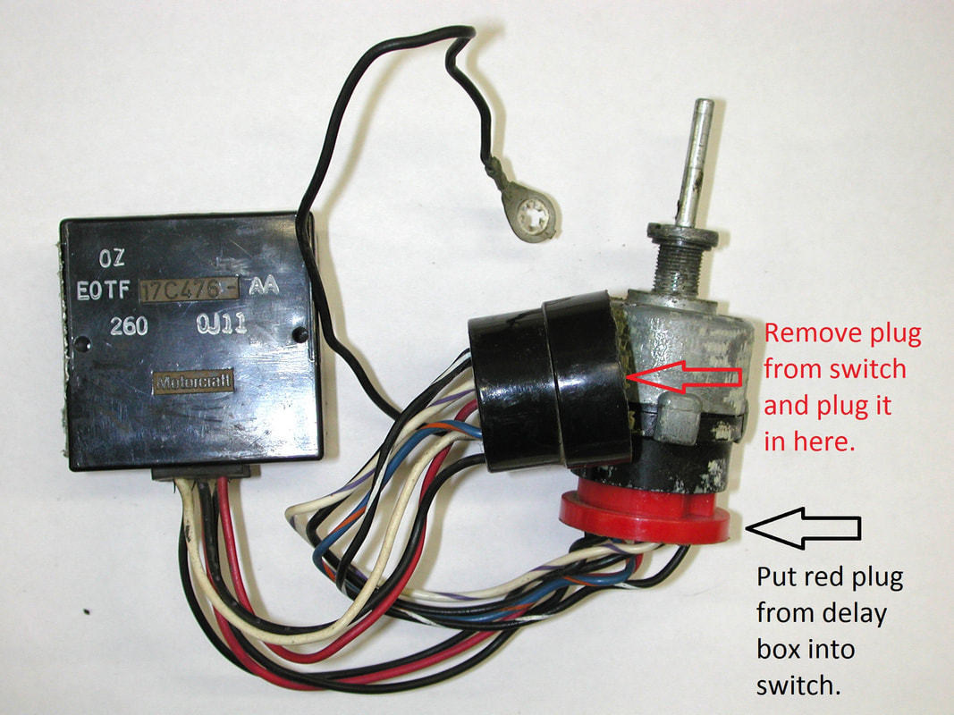
One of the best upgrades you can do for your Bullnose truck is to add the wiper delay feature. And it is really easy. All you need is the delay module and associated switch,shown below. That's it.
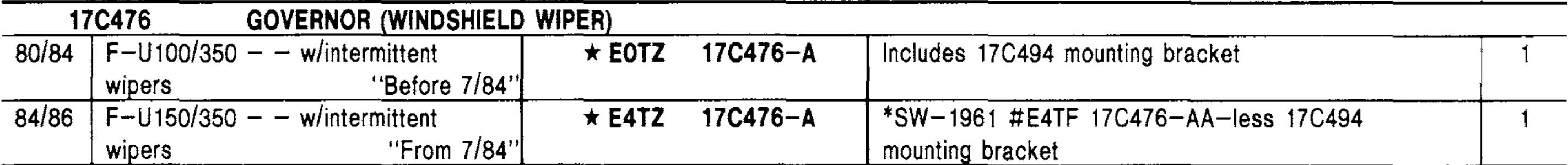
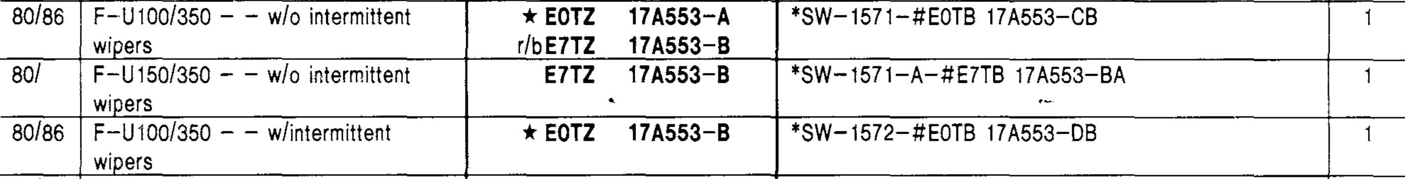
Note that the module shown is the 1980 version, as shown by the E0TF prefix on the engineering number. There are at least three other later versions that will work - a 1984 (E4), a 1987 version (E7), and a 1990 version (F0). So if you are junk yard shopping you don't need one specific to your truck. And the switch you are looking for is a EOTZ 17A553-B, and should be marked E0TB 17A553-DB. (The non-delay switch is EOTZ 17A553-A and is marked E0TB 17A553-CB, but that switch was replaced by E7TZ 17A553-B which is marked E7TB 17A553-BA.)
And as the notes in the picture show, you just unplug the existing harness from the existing switch, pull that switch and replace it with the delay switch, and plug the harness into the black plug on the delay module's harness. Then plug the red plug from the delay module into the switch, put the ground wire under a screw that provides a good ground, and you are almost done.....
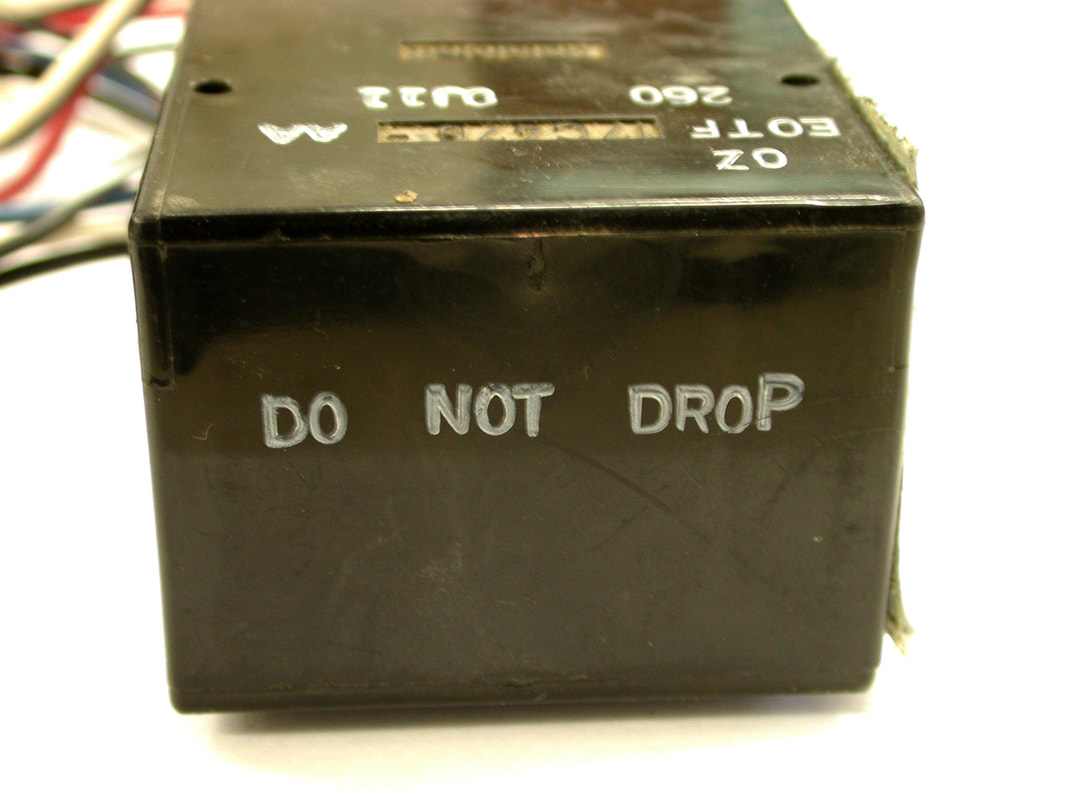
Almost done because you need to mount the delay module. However, note what it says on it - DO NOT DROP. Actually, what it should say is DO NOT JAR. The reason is that repeated jarring causes the solder joints inside it to crack and the unit to quit working. See the "Fix Your Delay Module" tab if yours has quit working. As for mounting, the best way is to wrap it in foam rubber and suspend it with a zip tie. That's because releasing the park brake sends shock waves through the dash, and is known to damage the module. So don't fasten it tightly to the dash, but do give it some padding.
Before getting too deep in troubleshooting the wipers it is best to understand the way they work. However, just in case it is a blown circuit breaker, which is housed in the windshield wiper switch, test the washer. If the washer doesn't work and the wipers don't work either then it is probably the circuit breaker and you will have to install a new switch.
But, let's assume that the washer works and the wipers don't. Now we are going to have to troubleshoot things. But before we do that we need some understanding of how things work. I recommend starting on the Regular Wipers (Start Here) tab, as the interval wipers are much more complex.
But, let's assume that the washer works and the wipers don't. Now we are going to have to troubleshoot things. But before we do that we need some understanding of how things work. I recommend starting on the Regular Wipers (Start Here) tab, as the interval wipers are much more complex.

Power Flow In High
Power Flow In Low
Power Flow In Park
|
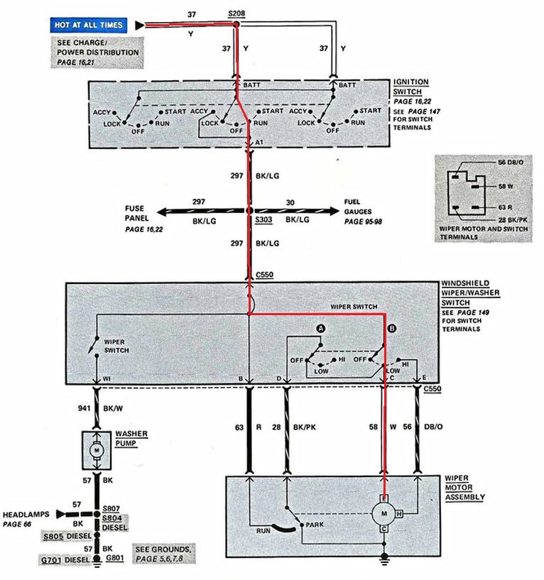
In High the power flows through the ignition switch in the Run or Accy positions, through the black/light green wire to the wiper/washer switch, through the circuit breaker, through the B arm of the switch and out on the dark blue/orange wire to the High terminal of the wiper motor.
In Low the power flows through the ignition switch in the Run or Accy positions, through the black/light green wire to the wiper/washer switch, through the circuit breaker, through the B arm of the switch and out on the white wire to the Low terminal of the wiper motor.
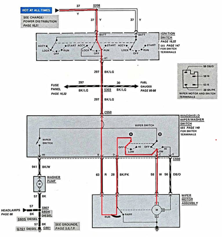
Ok, so the wipers are running and now you turn them off. What makes them go back to the Park position? In this case the power flows through the ignition switch as before, but when it gets to the wiper/washer switch it goes out to the motor on the red wire. Inside the motor housing it connects to a large electrical connection called a land, depicted next to the word Run in the drawing at the left. And there's an electrical wiper arm that goes around with the output shaft, and unless the output shaft is in the Park position that arm is touching the Run land, which feeds power out of the motor housing on the black/pink wire and back to the wiper/washer switch. There it goes through the contacts and comes back out on the white wire and into the motor on the Low terminal. And the motor runs until the output shaft gets to the Park position and the electrical wiper arm comes off the Run land. At that point the motor stops until you turn the wiper/washer switch to Low or High.
|
Interval Wipers High Speed
Interval Wipers Low Speed
Interval Power Flow
Interval Park Power Flow
|
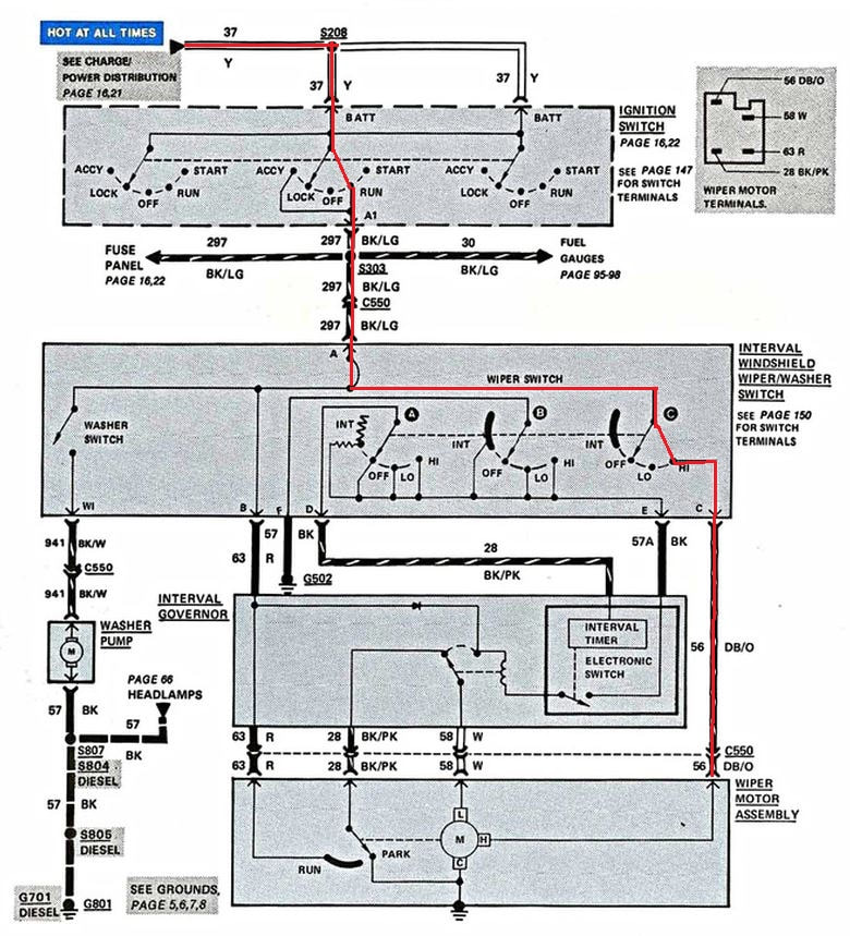
The interval wiper schematic is shown to the left, and the power flow for High is highlighted. And if you compare that to the flow for High on the regular wipers you'll find it is essentially the same.
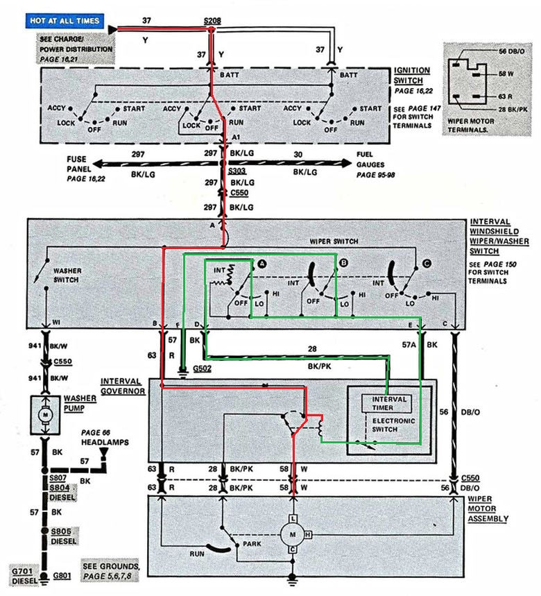
Now things get complex. In the schematic at left I've attempted to show the power flow in Low for interval wipers. Heretofore I've ignored the ground path as it was simple, but not anymore. In this schematic, as before, red indicates the positive side, but green indicates the negative side, and the negative side is convoluted.
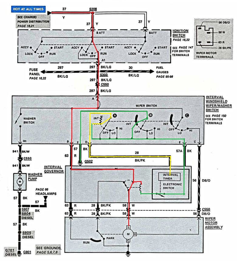
But, to explain, power comes in as usual through the ignition switch and goes into the washer/wiper switch on the black/light green wire. Then it comes out on the red wire and goes into the Interval Governor where it goes to a relay right in the center. When the relay closes, more on which in a moment, power flows to the wiper motor on the white wire to the low speed terminal. But, what pulls in the relay? The power goes to one end of the relay's coil and the other end is connected to ground via the Interval Timer and the wiper switch and its associated ground. And if that wasn't complex enough, let's look at the interval or delay position on the switch. This is almost identical to the Low position. However a variable resistance has been introduced. The yellow in the schematic indicates a voltage greater than ground but less than battery voltage, and that is what established the length of the delay. My guess is that the current produced charges a capacitor and at some pre-set voltage the electronic switch closes and that pulls in the relay. And when the relay closes the motor runs. However that probably discharges the capacitor and the cycle starts all over again.
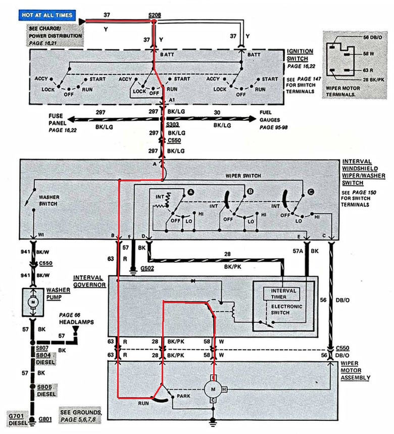
Fortunately the Park power flow is simple. As in the standard wiper circuitry the power flows to the Run land in the motor and any time the output shaft is not in the Park position power is fed out the black/pink wire into the Interval Governor. There, since the switch is off and the relay isn't closed, it flows to the motor's low speed connection and the motor runs until it gets to the Park position.
|
High-Speed Test:
Turn the ignition switch to On and place the wiper switch in the high position. Check for voltage at the circuit 56 (blue/orange wire) pin at the four-way connector. If no voltage is present, check voltage at circuit 297 pin (black/green wire) at the wiper switch. If voltage is not present trace circuit back to its source to determine problem. If voltage is present and motor does not run, ground the motor case to the body. If motor runs, repair ground. If motor does not run, replace motor.
Low-Speed Test:
Turn ignition switch On and place wiper switch in low position. Check for voltage at circuit 58 (white wire) pin at four-way connector. If no voltage is present, check voltage at pin #297 (black/green wire). If voltage is present at circuit 58, replace wiper switch, otherwise trace circuit back to source and determine problem. If voltage is present, and motor does not run, ground the motor case to the body. If motor runs, repair ground. If motor does not run, replace motor.
Park-Operation Test:
Turn ignition switch On and place the wiper switch in the Off position. Check for voltage at circuits 58 (white wire), 28 (black/pink wire), and 63 (red) pins at the four-way connector. If voltage is present on all three circuits and wiper blades are in the non-park position, ground motor case to the body. If motor parks, repair motor ground. If motor does not move to park position, replace motor. If voltage check shows only voltage at circuit 63 pin, replace wiper motor. If voltage check shows voltage at only circuit 63 and 28 replace wiper switch. If voltage is still not present at circuit 58, trace circuits 28 and 58 back towards wiper switch to determine source of problem.
Quick Test:
If wipers operate in high speed only (and wipers hesitate when going through Park position), connect jumper wire from windshield wiper switch case to ground. If wipers now work in low speed, repair the switch ground. If wipers do not work in low speed with switch case grounded replace governor.
High-Speed Test:
Place ignition switch in On position and wiper switch in high position. Check for presence of voltage at circuit 56 (blue-orange) pin. If voltage is present and motor does not run, ground motor case to body. If motor runs, repair motor ground. If motor does not run replace motor. If voltage is present at 63 pin (red wire) but not at pin 56 (blue/orange) replace the wiper switch. If no voltage present at pin 63 remove wiper switch connector and check 297 pin (black/green). If voltage present, replace wiper switch. If not, trace circuit back.
Low-Speed Test:
Place ignition switch in On and wiper switch in low position. Check for presence of voltage at circuit 58 pin. If voltage is present and wiper motor does not run, ground the motor case to the body. If motor runs repair motor ground. If motor does not run replace motor. If voltage is present at number 63 pin but not at circuit 58 pin, ground control circuits 57A (black) and 28A (black/pink) at wiper switch connection. If voltage is now present on circuit 58 pin, replace wiper switch. If voltage is not obtained at circuit 58 pin after grounding control circuits at wiper switch, replace governor. If no voltage is present at circuit 63 pin (red) remove the wiper switch connector and check for voltage at pin 297 (green/black wire). If voltage present, replace the wiper switch. If not, trace the circuit back.
NOTE: If governor relay is inoperative, wipers will operate in high speed and park only. Low and interval will not operate.
Interval Operation Test:
When the wiper switch is placed in the "INT" mode, the wiper motor oscillating park switch contacts are at ground, (assuming wipers started in park position), and the relay is energized. Initially, current flows from the ignition switch thru the circuit breaker in the wiper switch, through a diode and energized contacts in the governor to the wiper motor low speed brush. The motor rotates 1/10 of a cycle. The wiper motor oscillating park switch contacts then change from park (ground) to run (B+) and momentarily after they change position the relay in the governor de-energizes. A second path to the motor is shown by the arrows in Figure 3. The motor rotates through the remaining 9/10 of one cycle. When the oscillating park switch contacts again touch ground (park), the motor parks. The governor electronic circuit delays energizing of the relay until the circuit times out. Then the relay energizes and the low-speed interval is repeated. The discharge rate of the capacitor in the governor circuit to ground through the wiper switch variable resistor controls the time delay of the system.
Park Operation Test:
Place ignition switch in On position and move wiper switch from operating mode to off position. Check for presence of voltage at circuit 58 pin. If voltage is present and motor does not park, ground the wiper motor case to the body. If motor parks, repair ground. If motor does not run replace motor. If voltage is present at circuit 63 and 28 pins but not at circuit 58 pin, replace governor. If there is voltage on circuit 63 pin but not on circuit 28 pin, and the motor is not parked, replace the wiper motor. If no voltage is present on circuit 63 pin, remove the wiper switch connector and check for voltage at pin 297 (black-green wire). If voltage is present, replace the wiper switch. If not, trace the circuit back.
NOTE: Before troubleshooting the interval operating mode, the wiper system must be performing properly in low and park modes. If the wipers run continuously at low speed or the interval delay is excessive with the ignition switch On and the wiper switch in the INT position, remove the wiper switch and check continuity and resistance values. If switch ok, replace governor, otherwise replace wiper switch.
Wiper Motor Repair Tutorial
by Matt Wood
by Matt Wood
Hi Guys, I have decided to make a write up on repairing the wiper motor rather than replacing it. As some of you may know I live in the UK so replacement parts are much harder to get and a lot more expensive to ship over from the states. so I decided to attempt a repair on the motor myself.
The state my wipers were in...
I had High and Low speed but no park. which also meant that i had no intermittent as whenever the wiper relay module would click off the wipers would stop and go as they wished. After running through the trouble shooting steps from the EVTM and the repair to the wiper governor that Gary had written up I was still having the same issue.
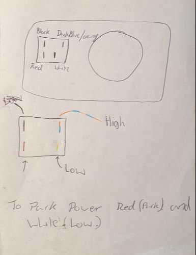
This lead me to manually testing the motor in place without the wiper switch and governor using a length of wire and some crimp connectors to the battery. Again i was able to get high and low speeds but no park. This is the very simple drawing i made to tell me what pin does what.
To Park, the 12V power must go to the red pin and a jumper must be placed between the black and white (low) terminals.
To Park, the 12V power must go to the red pin and a jumper must be placed between the black and white (low) terminals.
|
The reason there is no park is because of the motor itself, there is an armature similar to a relay arm inside the motor that shorts the red and black pins, this black pin (through the governor) provides power to the white (low) terminal. The gear inside the motor ASSY has a notch that actuates this armature (the park position 'brush') thus when the motor is not in park the red wire is supplying power to the black wire that spins the motor in the low position until the gear actuates the armature removing the connection stopping the motor in the 'park' position.
The Tutorial;
Step 1, remove the wiper motor from the truck
Step 2, Remove the 2 screws that retain the motor housing.
Step 1, remove the wiper motor from the truck
Step 2, Remove the 2 screws that retain the motor housing.
|
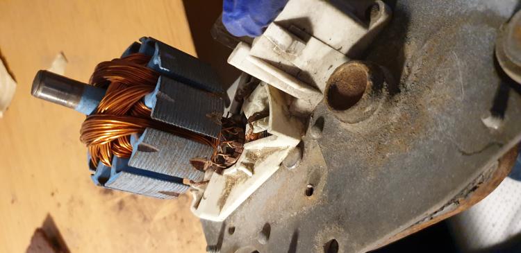
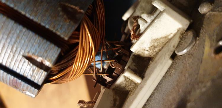
Step 3, Carefully remove the housing, don't be alarmed that all the brushes will ping lose, just be aware that the 3 springs are not attached and could go flying.
At this point you can put a multi meter between the red pin and the black pin and spin the wiper arm, this should give continuity (beep) at all positions and then be open circuit in the park position, however if the park isnt working then this wont be the case, the pins will be open circuit all the time.
At this point you can put a multi meter between the red pin and the black pin and spin the wiper arm, this should give continuity (beep) at all positions and then be open circuit in the park position, however if the park isnt working then this wont be the case, the pins will be open circuit all the time.
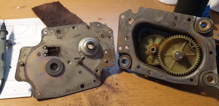
Step 4, Flip the ASYY over, Remove the 5 screws that hold the gear ASSY in place

|
Step 5, slide the backing plate off the gear, note that there is a small bushing that can fall out that goes at the bottom of the motor shaft, this must be put back if it falls out.
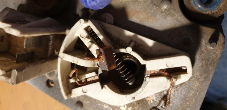
You should now be left with something that resembles this;
You should now be left with something that resembles this;
|
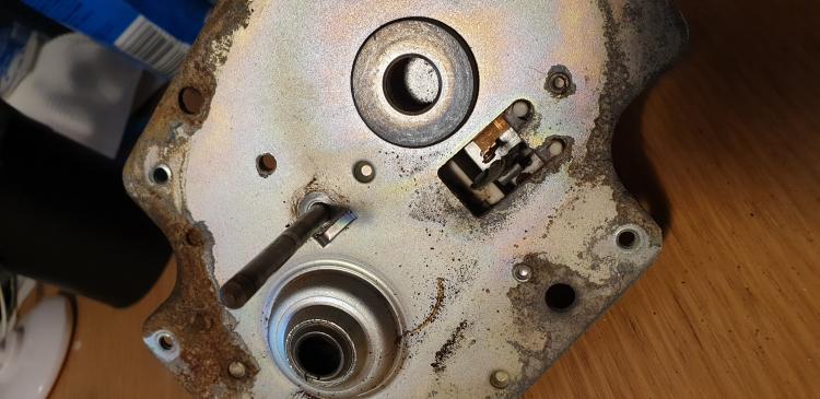
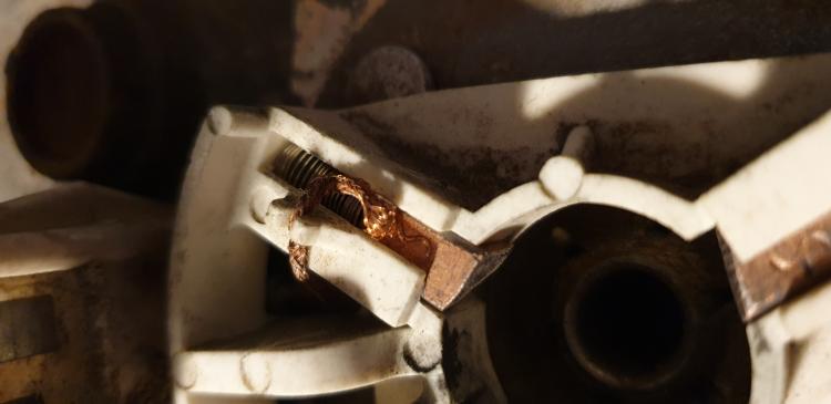
Step 6, you will see that on the backing plate there is an armature with a terminal either side,
This is the reason why the motor does not park. This will have corrosion on it and must be cleaned to gain proper operation.
This is the reason why the motor does not park. This will have corrosion on it and must be cleaned to gain proper operation.
|
Step 7, Simply get some fine sand paper and gently clean the pads on the terminals and on the armature itself. there is no need to force or bend anything here. the sand paper should be small enough to just slide between the pads, it will be tight on one side but you can still clean it carefully. you don't need to go mad here, it should only take a few wipes with the sand paper to clean the pads.
Step 8, Start to re assemble the backing plate and the gear ASSY. Make sure that bushing is still in place at the bottom of the motor shaft! Put all the screws into the gear ASSY at this point.
To realign the brushes simply use a small screwdriver or the probe of the multimeter to push the spring back into its guide and then slide the copper brush back in as well, then use the retaining clips build into the white casing to hold the copper wire to keep the brush back away from the shaft.
|
|
Step 9, Once the brushes are retained in place you can place the spindle into the hole, you will need to pull it out from the housing, don't worry its only the magnets holding it in! You may need to gently rotate the spindle to align the gears.
Before placing the spindle it is a good idea to check the circuit again for continuity on the red and black pins, the open circuit should now be at all but the 'Park' position. if it still doesn't stop beeping then go back and clean some more, manually move the armature while performing this test to make sure it could work then re assemble and test again.
|
It should slide down and seat on the bushing in the gear ASSY, there will be a plastic tab protruding from the back of the unit. If this is not the case then you will need to start again from Step 4 to put that back into place.
This is the spacing you should be left with once the spindle is back in place,
This is the spacing you should be left with once the spindle is back in place,
|
Step 10, Now pop the wires holding the brushed back out of place, all the brushes should be touching the spindle now.
Step 11, Place the motor housing back over the spindle, make sure you align it properly and place it in quick, the magnets will pull it together and removing it will mean you need to remove the spindle and realign the brushes. It will likely leave a small gap between the housing the the ASSY, you should be able to press this together, you shouldn't need to force it, if it wont go then take it apart and try again!
Step 12, replace the 2 screws that hold the housing in place, be sure to put the ground strap back into place else the motor will not work!
Step 13, Put the motor back into the truck and test, you may need to put direct power to the low terminal for the first start to realign the brushes and the armature. once this is done you can put the plug back in and enjoy working wipers!!!
Hopefully this will help others who were in the same situation as me, replacing the motor may not be necessary! this only took me about 15 minutes to accomplish so with the tutorial instructions above it should be easy for everyone.
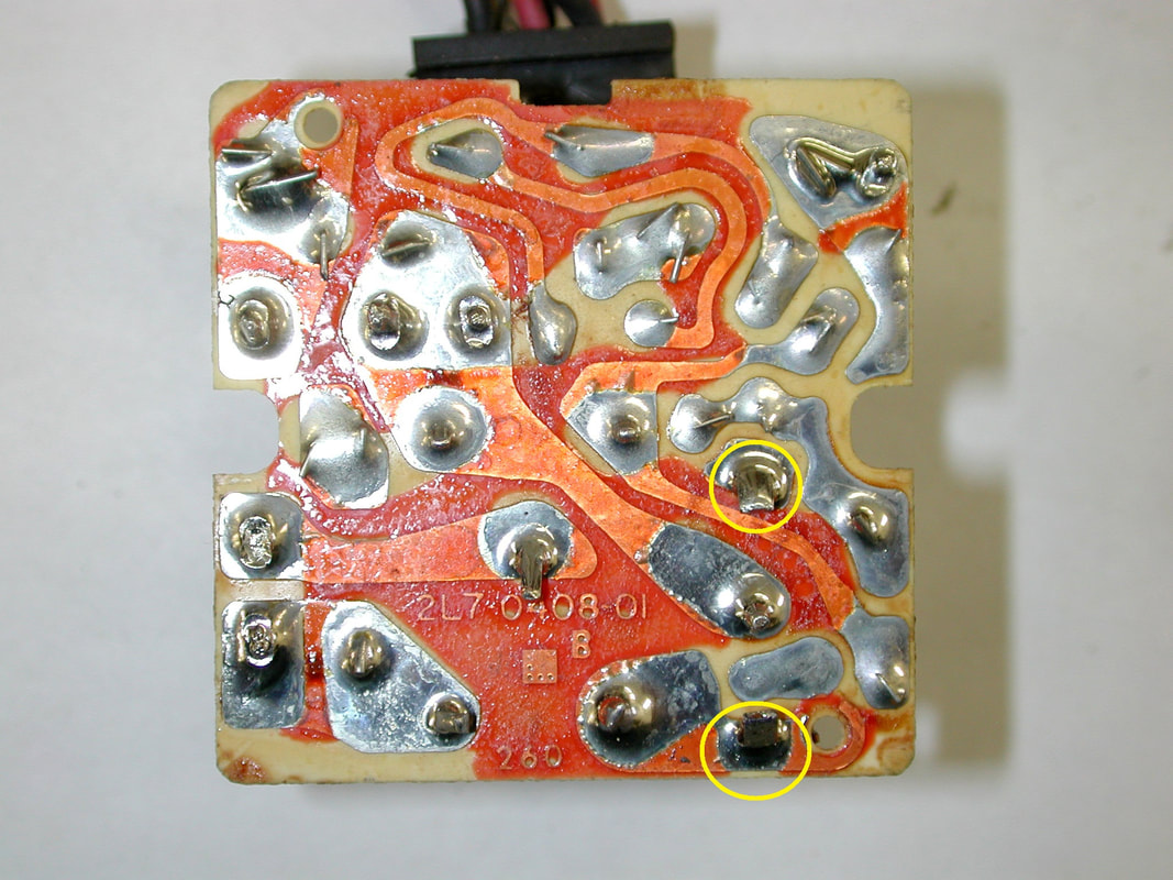
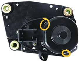
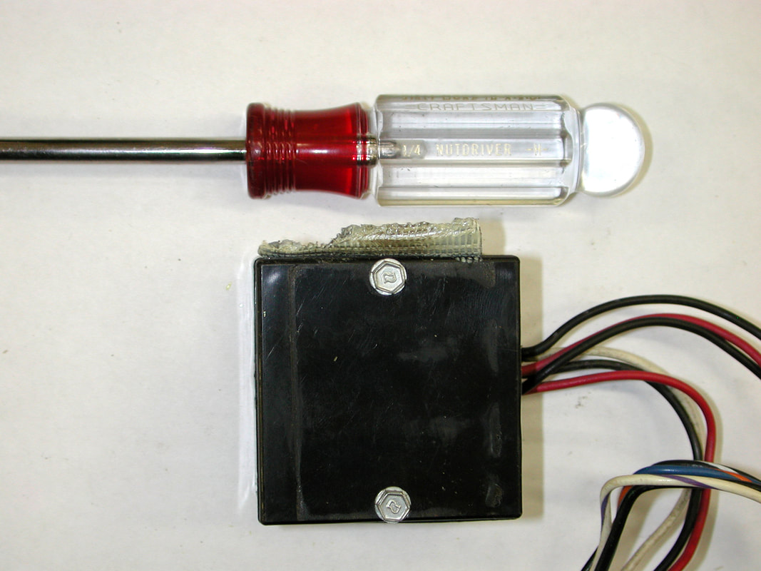
One known problem with the delay module is cracked solder joints due to repeated jarring, which was probably just releasing the park brake. But, fixing the broken joints isn't all that difficult. In the picture below you can see two screws that hold the lid on the module. Remove them and open up the module.
This is what it looks like on the inside, and the culprit is usually the solder joints for the heat sink.
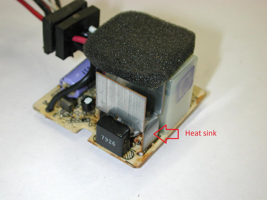
Turn the module over. The two heat sink joints are the ones circled in yellow, and you can re-solder them, or any other joint that appears to be broken. And, if that was the problem you can put it back together and enjoy delayed wipers yet again.