
3g alternator conversion - in development
swapping a 3g alternator IN place of a 1G or 2g alternator
By Michael Shumack: (Edited by Gary Lewis)
What’s the difference?
Early model trucks used a 1G (1st Generation) alternator with an external voltage regulator. This alternator put out 40 amps (single pulley) or 60-70 amps (double pulley). This system works fine for the power requirements of the early model trucks - but when additional electrical loads are added, like lights, stereo amp, winch, etc., the 1G alternator is underpowered.
In 1986 Ford started using the 2G (2nd Generation) alternator on the trucks. Ford replaced the 1G's external regulator in favor of the compact internal regulator design. However, the 2G series alternator has largely been considered the bad apple of the bunch. The flaw was in the power output plug and a weak bridge rectifier. The plastic power plugs used blade type terminals which would lose connection and occasionally melt, short, and possibly cause under-hood fires. In 1996 Ford publicly recognized the fire hazard caused by the 2G alternator and released TSB 96214.
Fords 3G alternator was a giant leap in technology and quality. Ford trucks starting using the 3G in the 1992 F-150. The 3G was internally regulated, used two internal cooling fans, sealed bearings, and had a superior battery stud. The 3G’s were more efficient, and produced more amperage at idle than any predecessor. In fact, a box stock 3G put out over 100 amps at idle as shown on our Alternator page and the DB Electrical 130A Test Results tab.
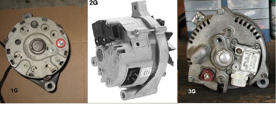 Ford 1G, 2G, & 3G alternators
Why Not?
If the 3G is so great, why wouldn’t I want to do this swap? There are a couple of reasons not to do this swap – or at least some additional considerations:
If the 3G is so great, why wouldn’t I want to do this swap? There are a couple of reasons not to do this swap – or at least some additional considerations:
- My electrical load is small (nothing added) so 40 - 70 amps is all I need.
- I have an ammeter in the dash, I don’t want to lose its functionality.
I want to do this swap, how do I start?
Ok, so you've decided that you are going to make the swap. So, what do you need? How do you start? First you need to get a 3G alternator, although on the Wiring It tab we will discuss the necessary "charge cable" and fuse.
Alternator: There are a couple of different case sizes of 3G alternators, different mounting locations, and even different hole-to-hole dimensions:
90A or 130A (or something bigger)?
The stock 3G comes in two frame sizes that originally had 90A & 130A ratings respectively, but there are companies providing upgraded units (most commonly) at 160A to 220A using the large case frame.
But keep in mind, a single V-belt drive can only support up to ~100A before the belt slips, and only then if the belt wrap and tension are sufficient. A double v-belt or serpentine belt can support up to a ~180A alternator. So if you go too large on the alternator output, you many need to improve your belt drive setup too.
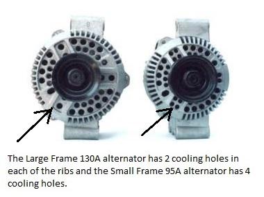
How to tell if it’s a small or large-frame unit: The number of cooling holes in the front that are in the three “ribbed” sections - two holes is the large frame, and four holes is the small frame.
Ok, so you've decided that you are going to make the swap. So, what do you need? How do you start? First you need to get a 3G alternator, although on the Wiring It tab we will discuss the necessary "charge cable" and fuse.
Alternator: There are a couple of different case sizes of 3G alternators, different mounting locations, and even different hole-to-hole dimensions:
- 90 Amp (small case) or 130 Amp (large case). And aftermarket units up to 220A.
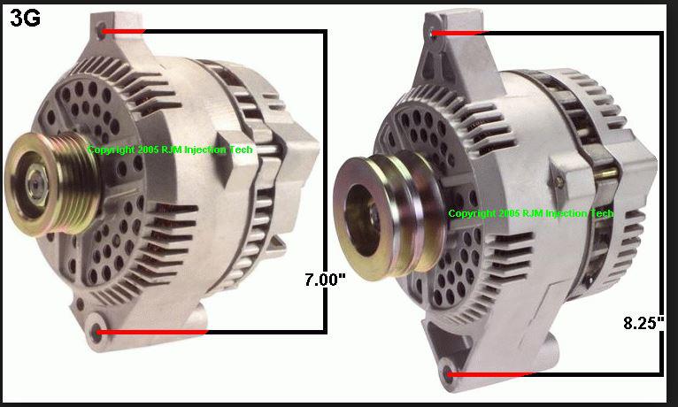
- Mounting ear locations: You need the mounts 180 degrees apart - 12 o’clock and 6 o’clock.
- Mounting ear lengths: There are 7” hole-to-hole, and 8.25” hole-to-hole cases. depending on which type of pulley system it uses. The one you need depends on whether your stock belt setup is V-belt or Serpentine.
90A or 130A (or something bigger)?
The stock 3G comes in two frame sizes that originally had 90A & 130A ratings respectively, but there are companies providing upgraded units (most commonly) at 160A to 220A using the large case frame.
But keep in mind, a single V-belt drive can only support up to ~100A before the belt slips, and only then if the belt wrap and tension are sufficient. A double v-belt or serpentine belt can support up to a ~180A alternator. So if you go too large on the alternator output, you many need to improve your belt drive setup too.
How to tell if it’s a small or large-frame unit: The number of cooling holes in the front that are in the three “ribbed” sections - two holes is the large frame, and four holes is the small frame.
* Trucks that currently have V-Belts use the 8.125” mounts, and trucks that have serpentine belts use the 7” mount spacing. (* Need to verify this info).

There is not much reason to go with the smaller 90A model, except that in some situations the larger frame 130A model may require some “clearancing” of the serpentine (aluminum) mounting bracket. If you don’t want to grind on your mounting bracket and 90A is all you need, then go with the smaller case alternator.
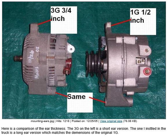
Also on a 1G to 3G swap, you may need to modify the tension-adjustment bracket for the V-Belt setups. The current bracket has a slight “offset” or jog to it. The bracket can easily be removed and “flattened” so that it fits behind the mounting ear.

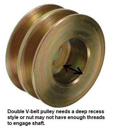
The pulleys can be swapped from 1G or 2G to a 3G. Putting a V-belt pulley on a 3G that has a serpentine belt pulley requires a small-thin shim under the pulley to keep V-pulley from rubbing on the 3G case.
Another Consideration - LRC:
There is at least one more things to consider - the voltage regulator. Remember that a single v-belt's limitations? Well, even two v-belts or a serpentine belt can be made to slip and squeal under heavy loads, especially if that load is applied suddenly. Fortunately there are voltage regulators that have Load Response Control built into them, and that really means that the regulator ramps up the alternator's output over the specified LRC time, which usually varies from 2.5 to 10 seconds. DB Electrical sells a model called AFD0028 that has LRC built in, which you can see on the test results of Jim/ArdWrknTrk's on the page here on the DB Electrical 130A Test Results tab.
So, where do I get a 3G alternator?
There are two approaches to this - get one from a salvage or some other used source, or buy a new one. If you are buying a used one the table below shows vehicles that would be good ones to look for, and the part number shows the alternator that should be in the vehicle. Also, the ID/Engineering # may be shown on the alternator.
As for buying a new one, that might be a very good option since you not only usually get a warranty, but you might be able to specify exactly what the alternator is. For instance, DB Electrical currently (2/8/2019) sells the F4PZ 10346-B from the list above for from $78 for a 130 amp unit up to $278 for a 220 amp unit - with a 1-year warranty.
Here is some info from the Quick Start Alternators page on the desirable alternators for a 3G swap:
|
Lester Nos: 7752, 7756, 7777
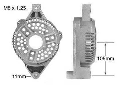
12:00 Mounting ear, M8 x 1.25 Thread, 148mm Diameter Large Case Used On:
|
|
Lester Nos: 7765, 7770, 7771
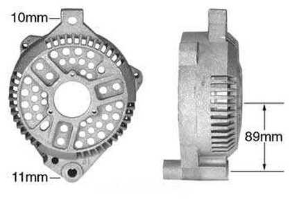
12:00, 10mm Mounting Ear, 148mm Diameter Large Case Used On:
|
|
Lester Nos: 7778
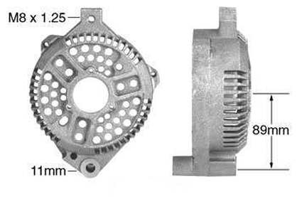
12:00, M8 x 1.25 Threading Mounting Ear, 148mm Diameter Large Case Used On:
|
Clocking:
The back of the alternator can be attached to the front of the alternator in three different positions, and those positions are called the "clocking" of the alternator. The industry standard for referencing clocking appears to be with the pivot at 6:00 and the clamp arm at 12:00, as shown in the picture above. So in the picture above the alternator has 7:00 clocking, but it could have 4:00 or 11:00 clocking since the positions go in 4-hour increments [12 hours/3 positions]. (Other alternators may have different clocking - I don't know.)
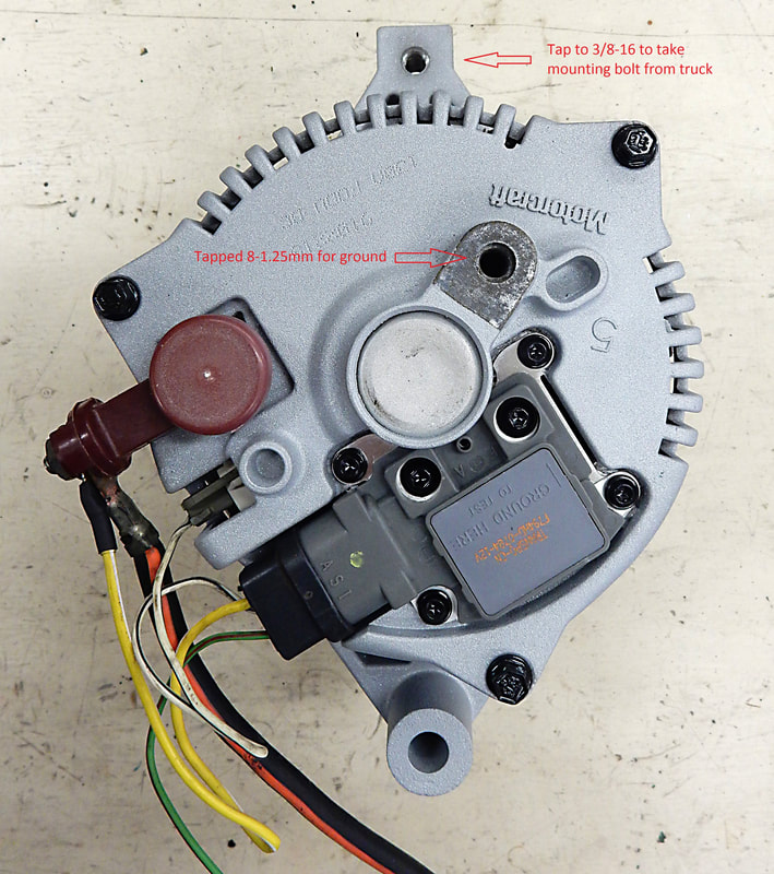
As you can see in the picture below, which is the same alternator as above before being powder-coated and having 160 amp diodes installed, the regulator connector is pointing almost straight up and the B+ terminal for the charge cable is handy to the left, although in that picture it doesn't yet have the extension on it, which brings the stud to the top. Anyway, if that orientation doesn't work for you then you can rotate (re-clock) your alternator, and Steve83's instructions for doing so are here.
The back of the alternator can be attached to the front of the alternator in three different positions, and those positions are called the "clocking" of the alternator. The industry standard for referencing clocking appears to be with the pivot at 6:00 and the clamp arm at 12:00, as shown in the picture above. So in the picture above the alternator has 7:00 clocking, but it could have 4:00 or 11:00 clocking since the positions go in 4-hour increments [12 hours/3 positions]. (Other alternators may have different clocking - I don't know.)
As you can see in the picture below, which is the same alternator as above before being powder-coated and having 160 amp diodes installed, the regulator connector is pointing almost straight up and the B+ terminal for the charge cable is handy to the left, although in that picture it doesn't yet have the extension on it, which brings the stud to the top. Anyway, if that orientation doesn't work for you then you can rotate (re-clock) your alternator, and Steve83's instructions for doing so are here.
Ok, you've decided you are going through with the swap and you've picked the alternator, so what else is needed? Specifically, three things - a 3G harness, some sort of circuit protection, and a decision on what changes to make to your existing wiring. See the tabs below to help you with those three things, but pick either the 1G Wiring Changes tab or 2G Wiring Changes tab based on your truck's wiring. (Up through 1985 should be 1G, and 1986 through 1991 should be the 2G.)
|
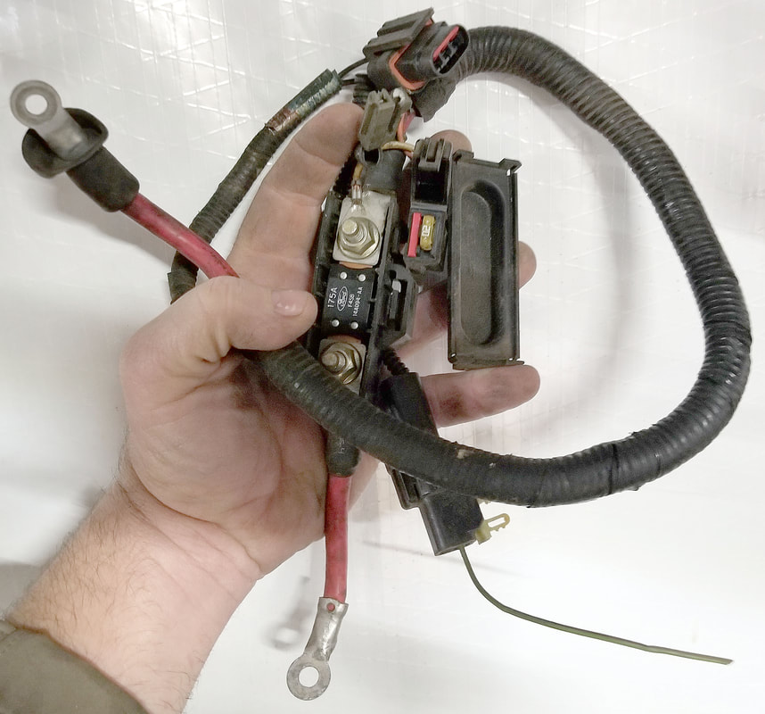
An easy place to get the 3G harness is at the salvage. To the right is a picture that Steve83 took of a complete harness that has everything you need. In that pic his thumb is on the output cable coming from the alternator and it is pointing at a 175 amp fuse in a nice holder that can be mounted on your inner fender near the starter relay. And his pointer finger is touching the stator connector and pointing at the regulator connector. Everything you need in one go.
But, there are other Ford harnesses available. Here's one I found on a Ford in the salvage. In this one you can clearly see the white/black stator wire coming out of the alternator and wrapping back to go into the alternator at the regulator plug. And, you can see the yellow/white that comes from the regulator's plug and is connected to the big output terminal. (If you look closely, in the picture above the yellow/white wire connects to the alternator side of the fuse and is protected by the 20 amp fuse in the fuse holder.) But, my harness does not have a fuse, and some form of circuit protection is necessary. See the Circuit Protection tab. And in both cases you can see the light green/red wire that is headed back to the light green/red wire in the truck's existing harness. |
|
But, if you didn’t get the wiring with the alternator, you can buy it. There are several companies making/selling it, including:
Ok, let's summarize the wiring. There are only four wires, not including the ground:
Grounds:
In the picture of the alternator above note that the ground connection, which is tapped 8-1.25mm, was not powder coated. Nor were the threads in the ear at the top. That's because current from the alternator also has to return, and without a solid return path the alternator cannot work properly.
Given that, none of the surfaces that will be part of the mechanical attachment of the alternator, and therefore the ground path, should be painted or coated - or they should be cleaned down to shiny metal if they are. But, another option is to add a ground wire, the same size as the charge cable itself, from the case of the alternator to the engine block .
- Quick Start: This is the regulator and stator wire wiring, but you'll have to supply your own charge cable
- Ron Francis: This kit has the regulator and stator wiring as well as wire for the charge cable
- Painless: This kit has everything, including a 150 amp fuse and holder
Ok, let's summarize the wiring. There are only four wires, not including the ground:
- I: Light green/red wire that tells the regulator that the key has been turned to On. This wire will connect to your original light green/red wire, regardless of whether your truck has an ammeter or warning lights.
- A: Yellow/white wire that tells the regulator what the alternator's output voltage is. It can go directly to the output stud of the alternator or it can go to the alternator's side of the fuse/fuse link.
- S: Black/white stator output and that wire wraps back to the middle terminal on the regulator's plug. But, if you have an electric choke be sure to see the Choke tab, above.
- B+: Orange/black wire that is the output for the alternator and should be wired through the fuse described above to the battery side of the starter relay, frequently called the "solenoid". But not back to the existing black/orange wire in your Bullnose harness!
Grounds:
In the picture of the alternator above note that the ground connection, which is tapped 8-1.25mm, was not powder coated. Nor were the threads in the ear at the top. That's because current from the alternator also has to return, and without a solid return path the alternator cannot work properly.
Given that, none of the surfaces that will be part of the mechanical attachment of the alternator, and therefore the ground path, should be painted or coated - or they should be cleaned down to shiny metal if they are. But, another option is to add a ground wire, the same size as the charge cable itself, from the case of the alternator to the engine block .
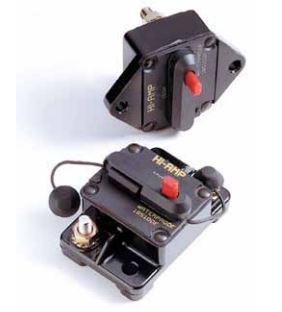
As said, some form of circuit protection is necessary, and that could be a fuse link, circuit breaker, or a fuse. On some later trucks, like '96, Ford used a fuse link, but on other vehicles they used a fuse, and when a fuse was used with the 130 amp alternators it was a 175 amp unit. But, if you're going with a higher-output alternator then you should scale up the fuse as well. And, if you didn't get a fuse holder with your harness you can buy a separate one, or even a circuit breaker, with examples shown below.

|
|
Now click on the tabs below for schematics and discussions on how to connect your 3G to your existing wiring.
If you have a truck with the factory ammeter in the dash you should convert it to a voltmeter. That is because the higher output of the 3G alternator is too much current for the stock ammeter's shunt, which is probably only good for 70A since that's the size of the largest alternator that was available in these trucks. That's why you must move the alternator's output to the battery side of the starter relay, as shown in the schematics that follow or you are highly likely to melt the shunt.
But by moving the alternator's output the ammeter will no longer be "seeing" the current flowing into the battery. In fact, what it will be "seeing" is the load of the electrical system, such as the ignition, lights, heater or A/C fan, etc. So, all you will see on the ammeter is discharge, even when the alternator is keeping up with the demand. (Saying it another way, with nothing on in the truck the ammeter will sit in the center, but when you start bringing accessories on it'll swing to the discharge side - whether or not the alternator is working.)
The recommended alternative is to convert the factory ammeter to a voltmeter. RCCInnovations will convert your factory ammeter into a voltmeter for $40. It will still have “D” and “C” and not the actual voltage readings, but it will show you if your alternator is charging and the state of your battery.
However, you will need to re-wire in order to use it. And in doing that you need to ensure that the voltmeter isn't on all the time as it pulls ~80ma, so it should only be on when the key is on or it will drain the battery. And, you'll have to decide if you want to monitor the voltage of the battery or the voltage in the cab, and those are two different things, as explained on a later tab.
Up through 1985 Ford used the 1G alternator, but in 1986 the 2G was introduced. And since their wiring is slightly different each other we've provided a tab for each. Click on the one you have.
There are essentially two sources of power for the voltmeter - from the ignition switch or from the battery itself. And while they might seem to be the same they really aren't. The difference is due to the resistance in the factory wiring, connectors, and switches which means that monitoring the voltage at the ignition switch will show a lower voltage than monitoring at the battery. And, more importantly, it will change as you turn on more devices in the cab.
On the other hand, monitoring the voltage at the ignition switch is easier to do than monitoring at the battery, which requires a relay, so we will present both methods and you get to choose.
On the other hand, monitoring the voltage at the ignition switch is easier to do than monitoring at the battery, which requires a relay, so we will present both methods and you get to choose.
The easiest approach is to simply use the LG/R wire that comes from the ignition switch to provide power to the volt meter. It will work very well, but the more current you draw in the cab the lower your voltage will appear to go on the gauge. (We really ought to have Scott measure his voltage in the cab vs at the battery in various conditions and see what the voltage difference really is.)
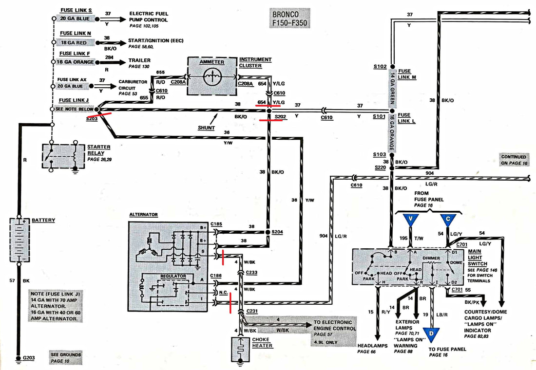
The schematic below shows how to wire it:
The schematic below shows how to wire it:
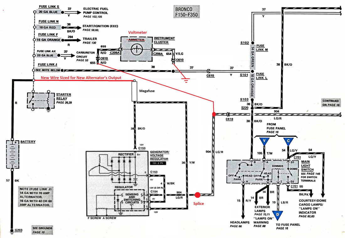
This is what the schematic looks like for your truck before you start, but the red lines show where to cut what wires:
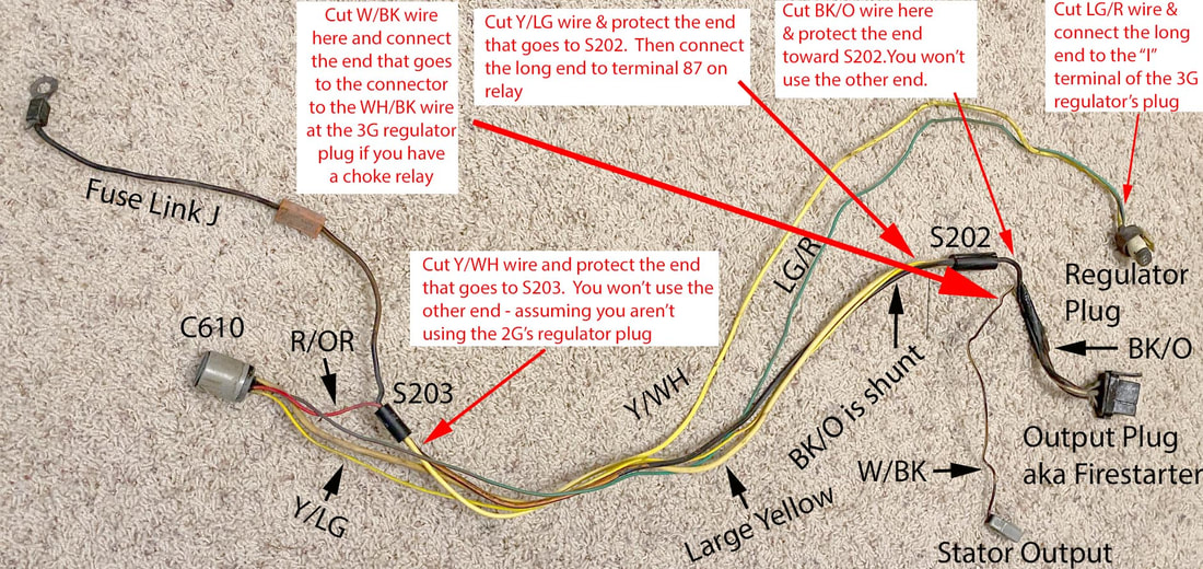
And here's what the wiring harness looks like, with the cut points noted:
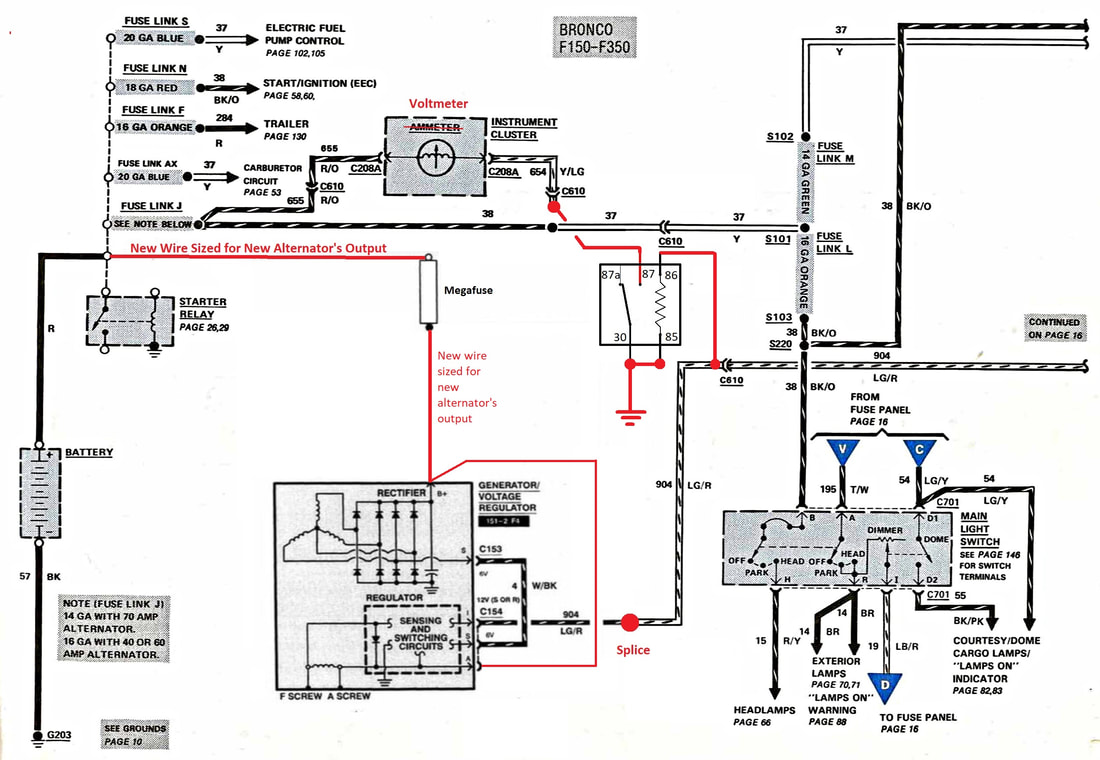
And here is what the final circuitry will look like. Note that a relay is required to ensure that the voltmeter isn't powered 24x7 or it will ultimately drain the battery. A standard Bosch style relay is more than adequate.
As said, if you have a truck with the factory ammeter in the dash, you should convert it to a voltmeter. That is because the higher output of the 3G alternator is too much current for the stock ammeter's shunt, which is probably only good for 70A since that's the size of the largest alternator that was available in these trucks. That's why you must move the alternator's output to the battery side of the starter relay, as shown in the schematics on the other tabs, or you are highly likely to melt the shunt, and probably melt it into other wires in doing so.
But by moving the alternator's output the ammeter will no longer be "seeing" the current flowing into the battery. In fact, what it will be "seeing" is the load of the electrical system, such as the ignition, lights, heater or A/C fan, etc. So, all you will see on the ammeter is discharge, even when the alternator is keeping up with the demand. (Saying it another way, with nothing on in the truck the ammeter will sit in the center, but when you start bringing accessories on it'll swing to the discharge side - whether or not the alternator is working.)
The recommended alternative is to convert the factory ammeter to a voltmeter. RCCInnovations will convert your factory ammeter into a voltmeter for $40. It will still have “D” and “C” and not the actual voltage readings, but it will show you if your alternator is charging and the state of your battery.
However, you will need to re-wire in order to use it. And in doing that you need to ensure that the voltmeter isn't on all the time as it pulls ~80ma, so it should only be on when the key is on or it will drain the battery. And, you'll have to decide if you want to monitor the voltage of the battery or the voltage in the cab, and those are two different things.
There are several different approaches to wiring the voltmeter up, but we are going to recommend only two:
|
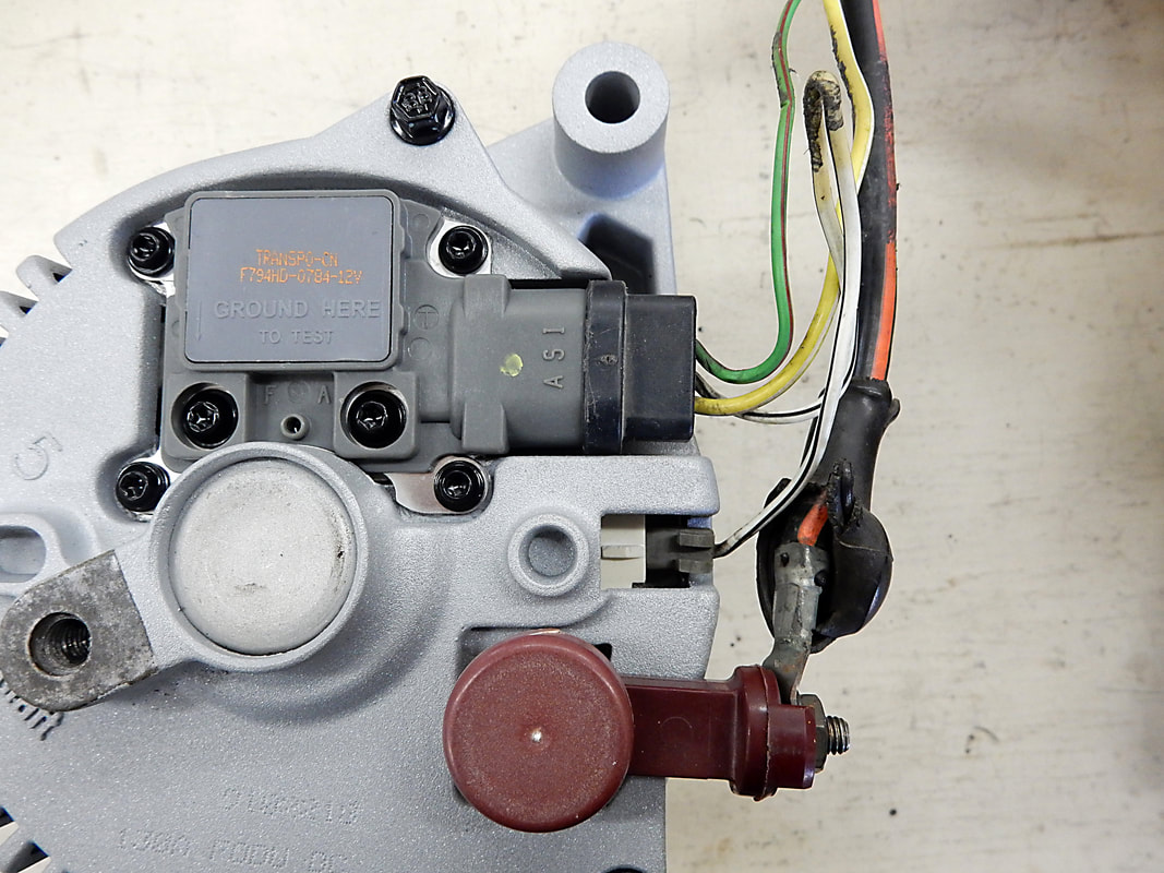
There are two versions of electric chokes: those that run on 7 volts and those that run on 12 volts. If you have a 7 volt choke there's no need to change it when doing a 3G conversion. That's because the 3G alternator still provides the "stator" connection like the 1G's and 2G's do, which is what runs the choke. That wire will be the white/black wire, which is shown in the picture to the right. So if you are using a 7 volt choke just connect your existing choke wire, which should also be white/black, to that wire. (Note: If you are using an aftermarket cable it may be a different color, but it will still be the wire that comes from the middle connector and goes to the middle of the regulator's connector.)
|
|
But, if you have a 12 volt choke, like on an Edelbrock carb, then you may want to change things. I say that because it is possible to run a 12v choke on the stator's output, but it takes longer for the choke heater to get warm enough to cause the choke to fully open. And that means you may have to run the choke leaner than you want in order for it to come off fully on short trips.
|
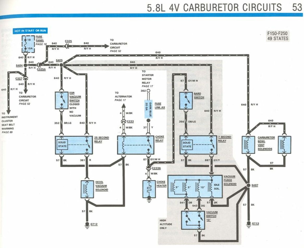
If you happen to have a factory 351HO then the problem is solved as those trucks have a choke relay which is pulled in by the output of the stator on the alternator, as shown in the middle of the schematic to the right. (Click it to get a bigger view.)
|
|
|
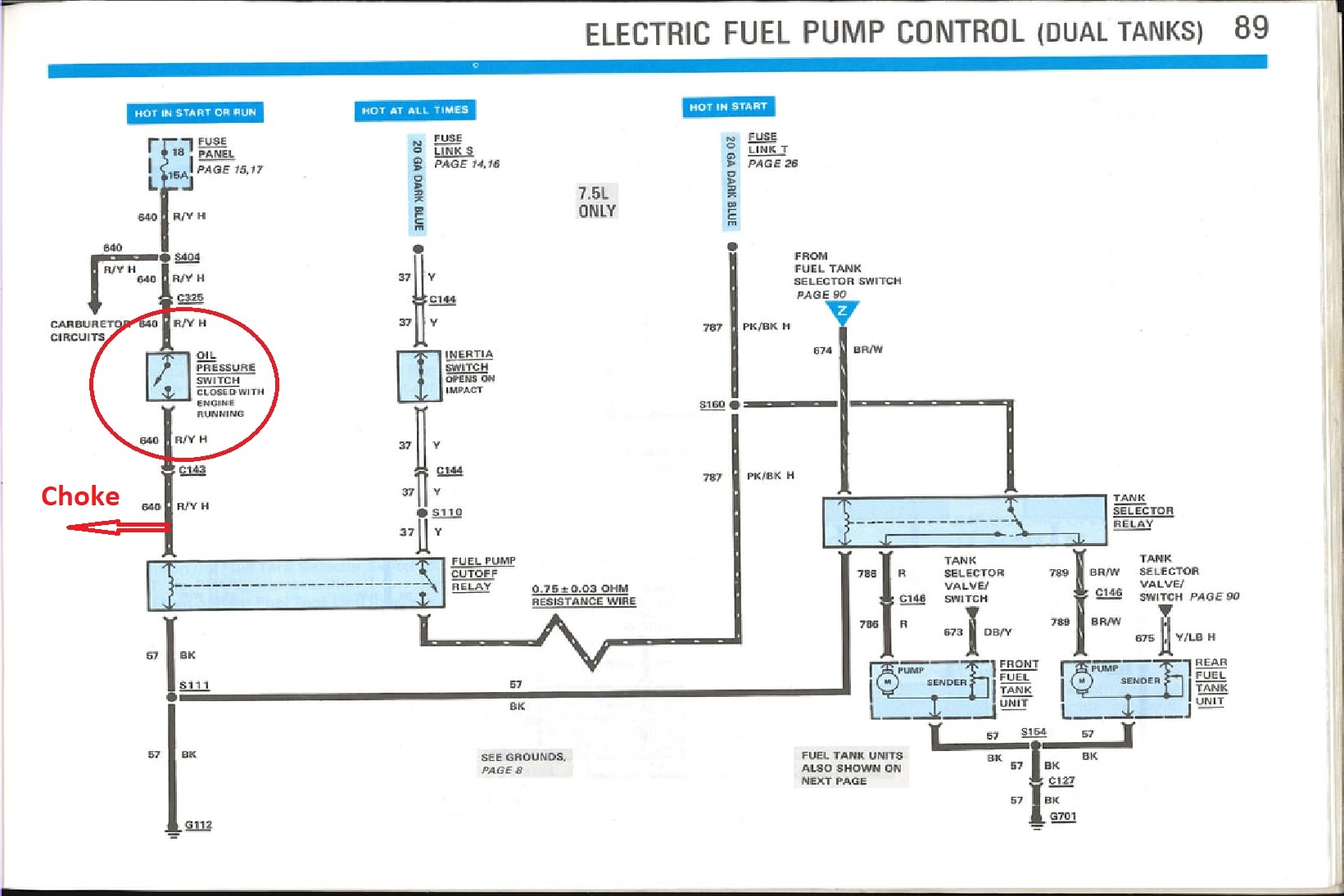
Or, if you have a factory 460 you may have an easy solution. That's because some of those trucks had in-tank fuel pumps with a fuel pump relay and you can tap into that for the choke heater, as shown to the right.
|
|
|
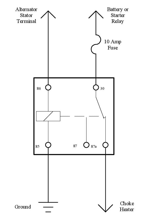
But, if you don't have either of those setups you can still easily add a relay to power the choke. Having said that, there are a several ways to do that. I believe the best way is to power the choke only when the engine is running, and that means that it won't be on when you turn the key to Run or Accessory. And the easiest way to do that is to use the stator's output, which is quite capable of pulling in a standard relay.
The drawing to the right depicts one way of doing that. The components recommended are:
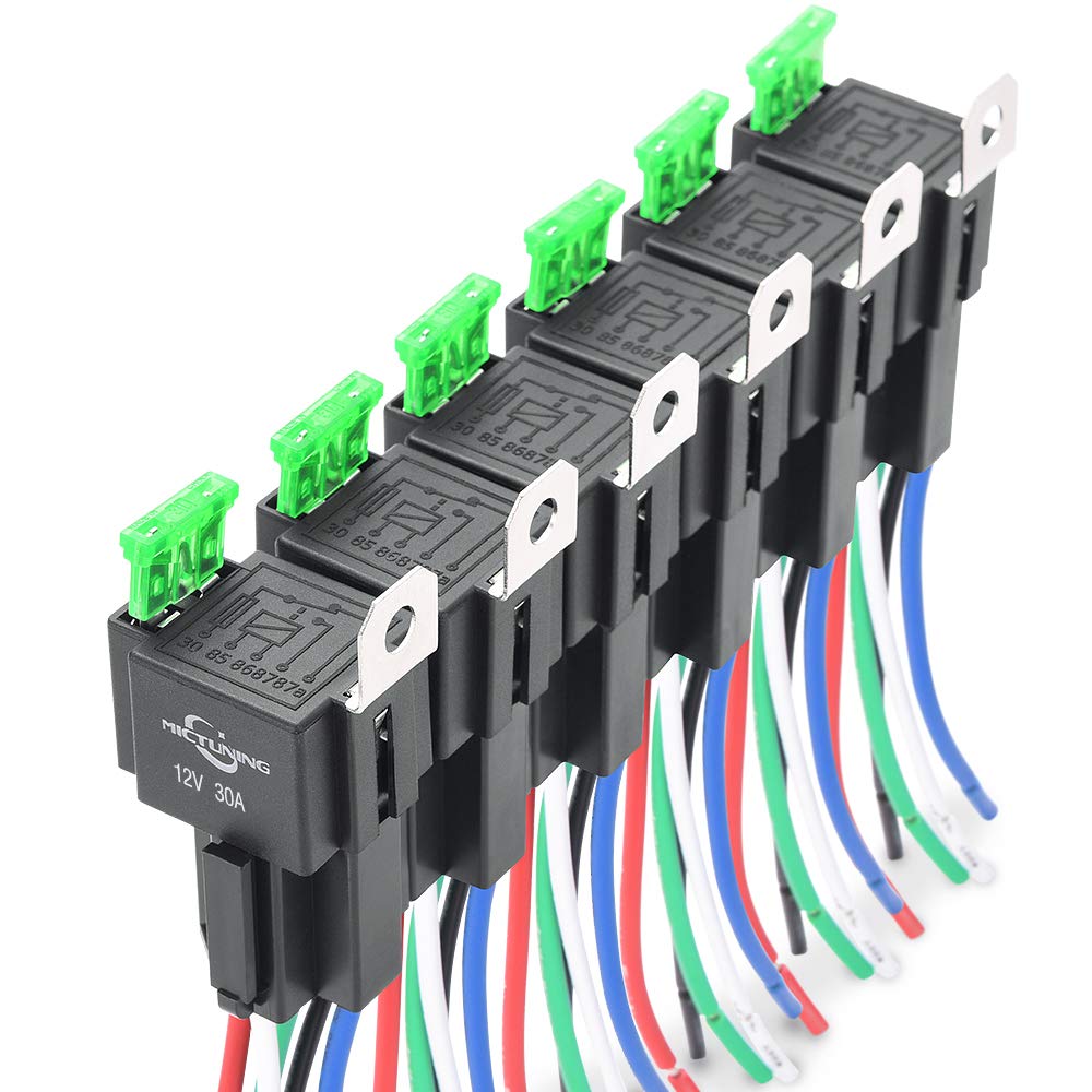
As for the relay, fuse holder, and socket you can see that by the time you buy each item you'll be in the $20 range. And since that's basically the price of the 6-pack of relays with socket and integrated fuse, shown below, I think it is a reasonable option. So let's proceed assuming that is what you'll use. The schematic in the middle, below shows how to use the wires on the Mictuning relays:
|
|
|

|

|