brakes
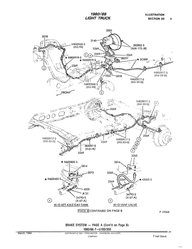
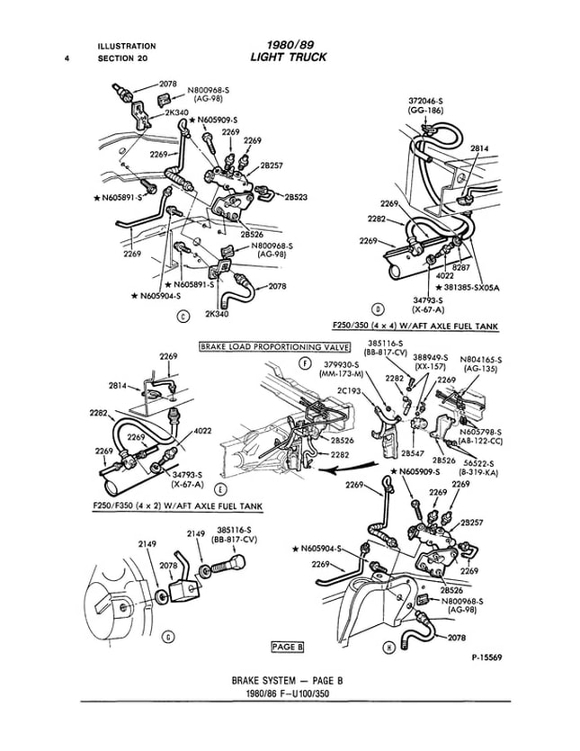
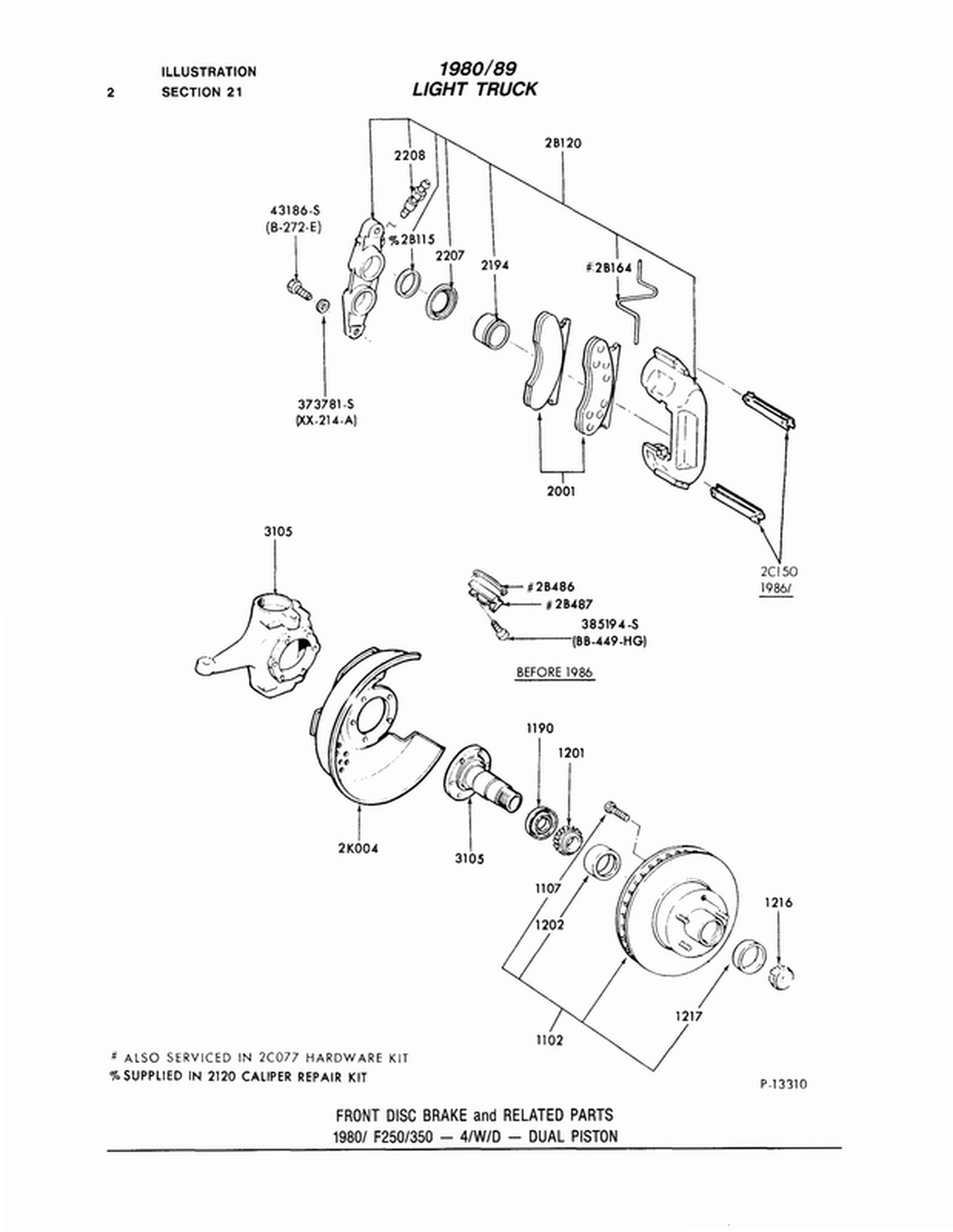
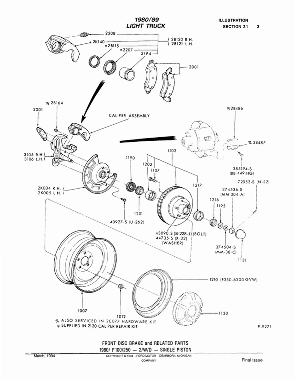
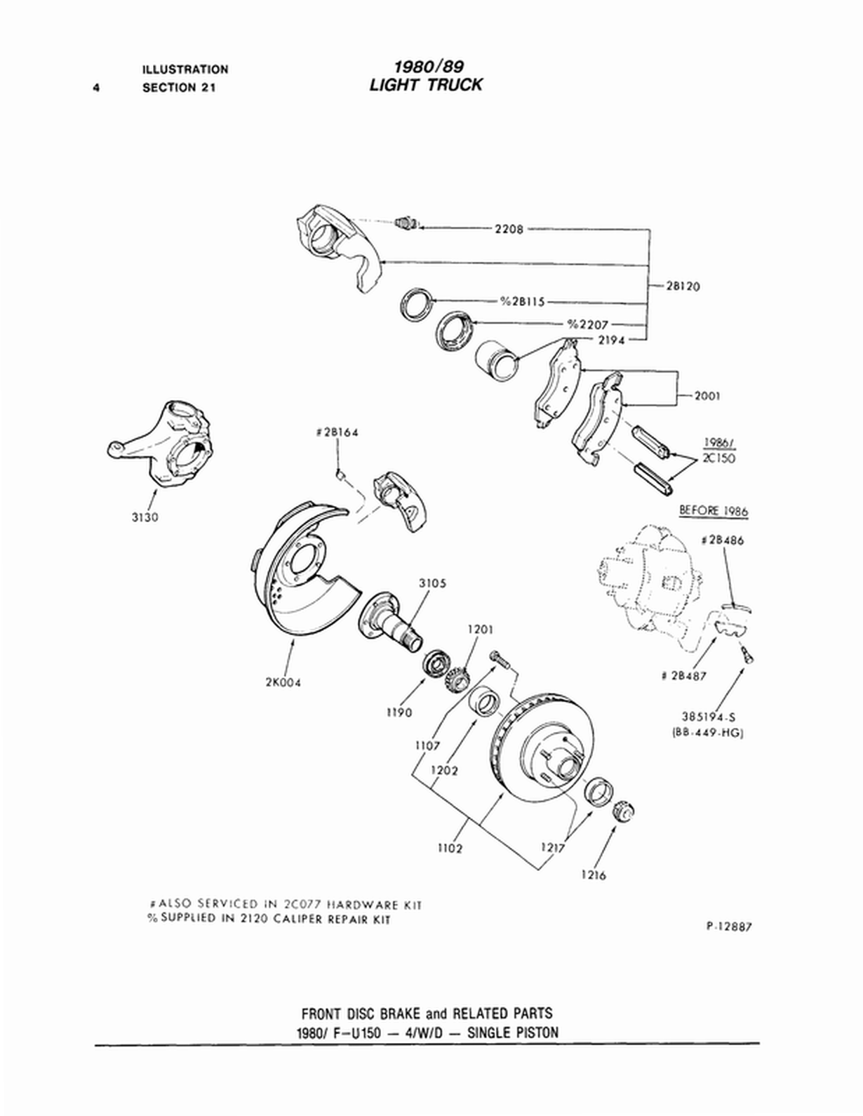
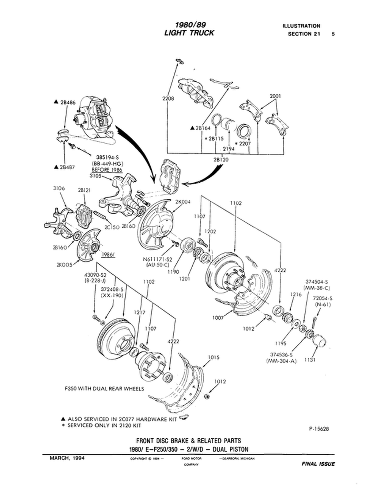
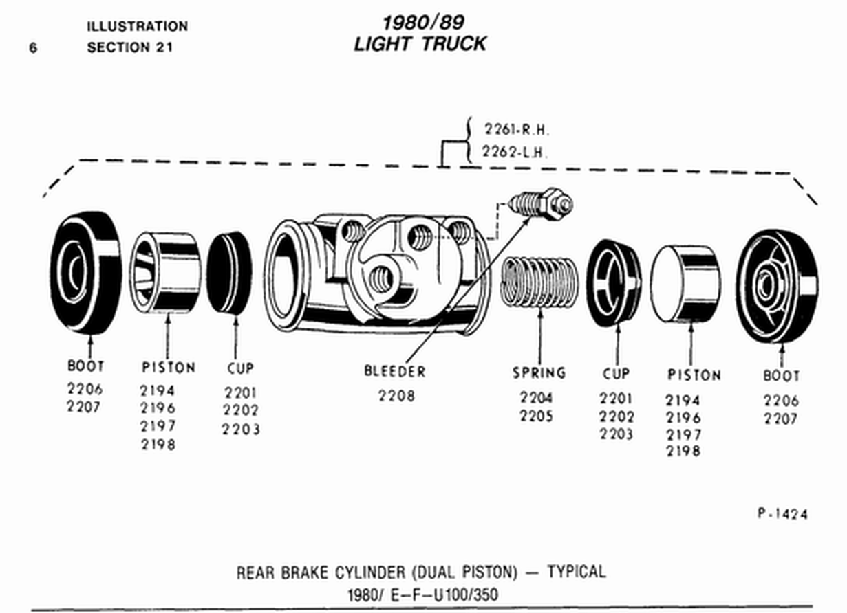
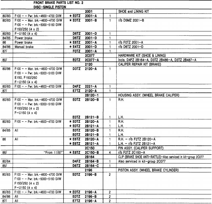
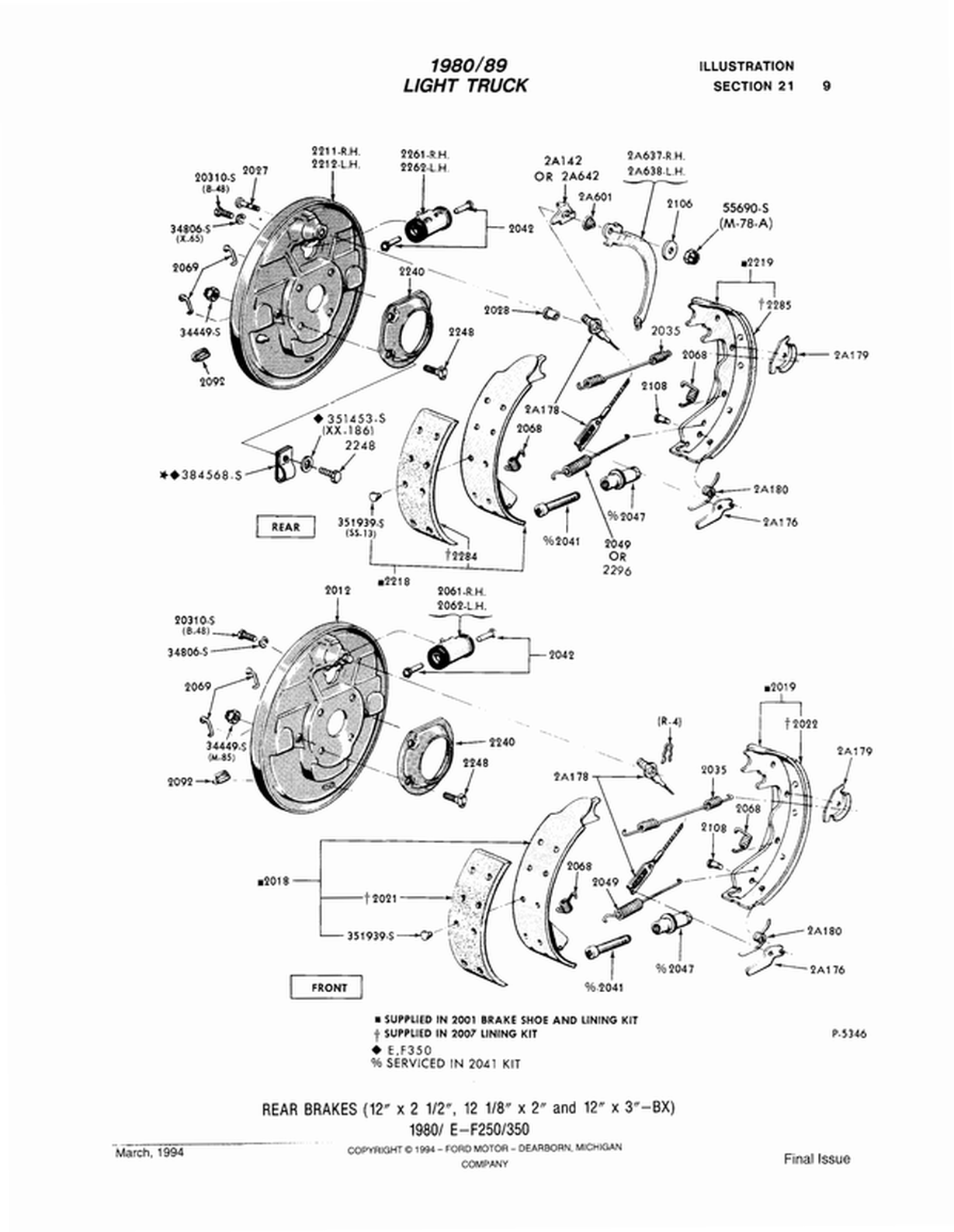
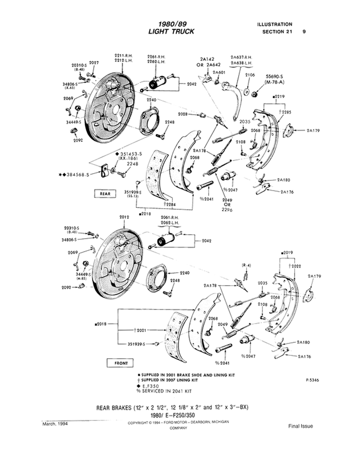
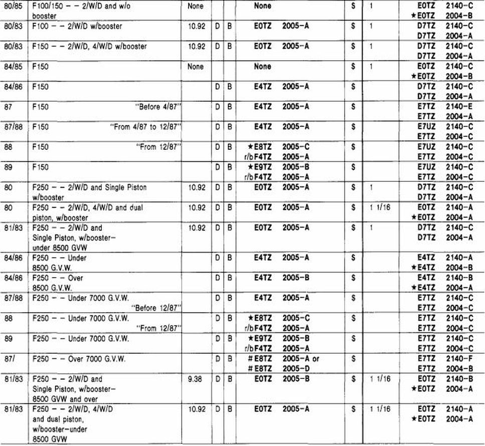
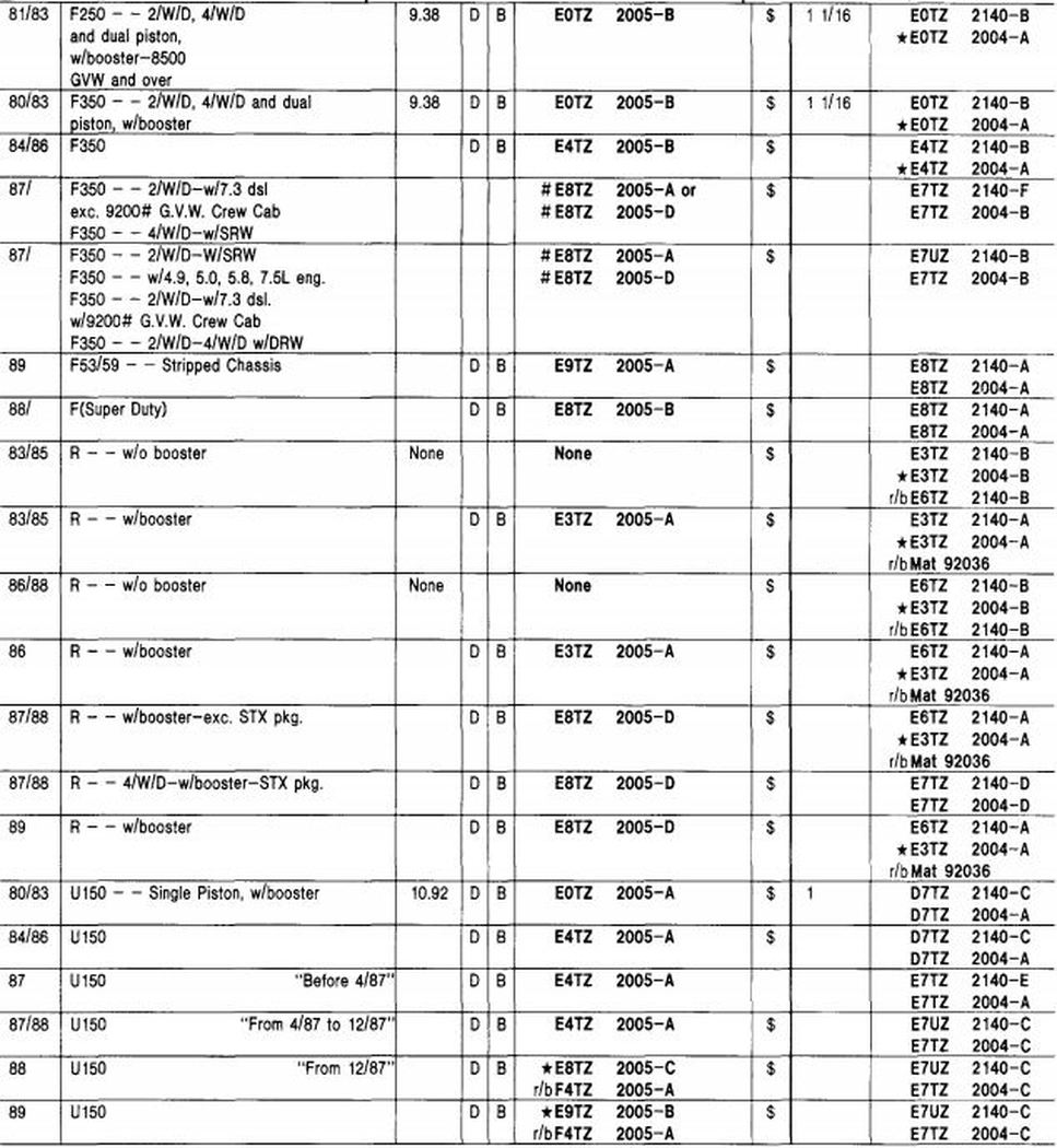
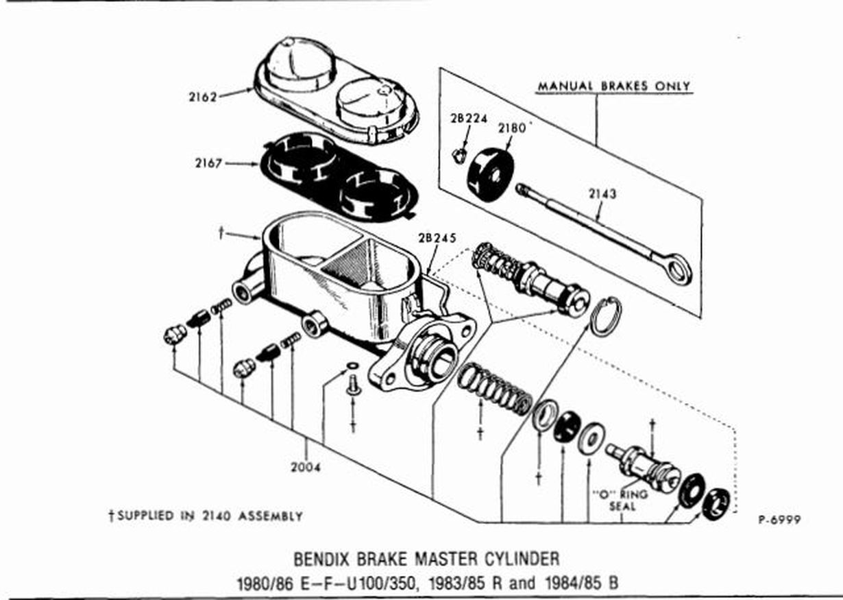
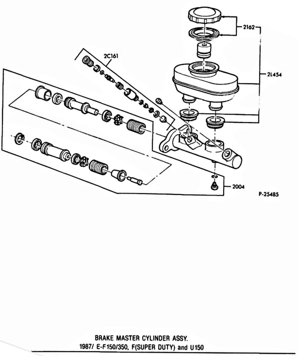
Factory shop manual sections as well as illustrations & part #'s from Ford's Master Parts Catalog for the brakes, master cylinders, boosters, brake pedals, proportioning valves, and dust shields used on the 1980 - 86 Ford trucks.
Push Rod Adjustment
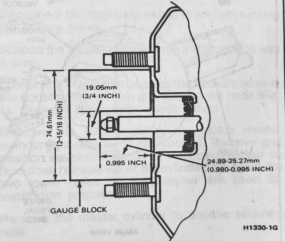
The push rod has an adjustment screw to maintain the correct relationship between the booster control valve plunger and the master cylinder piston. If the plunger is too long it will prevent the master cylinder piston from completely releasing hydraulic pressure, causing the brakes to drag. If the plunger is too short it will cause excessive pedal travel and an undesirable clunk in the booster area. Remove the master cylinder for access to the booster push rod.
To check the adjustment of the screw, fabricate a gauge and place it against the master cylinder mounting surface of the booster body as shown in Fig 2. Adjust the push rod screw by turning it until the end of the screw just touches the inner edge of the slot in the gauge.
(From Ford's 1985 Truck Shop Manual, Page 12-50-1)- Brake pedals, bracketry, et al are described on the Clutches And Linkage page and on the Clutch Linkage tab. Sorry for the inconvenience.
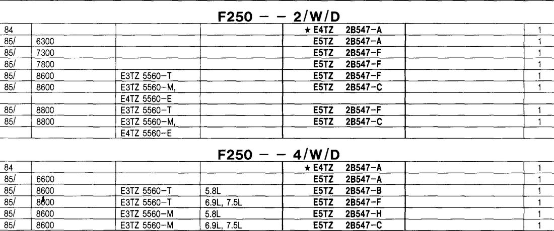
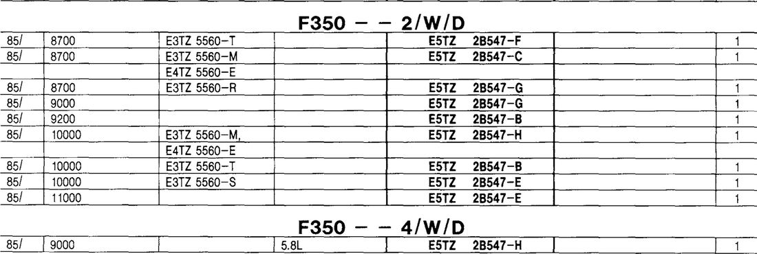
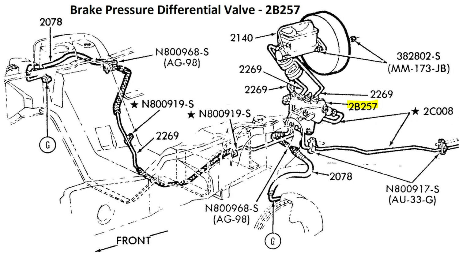
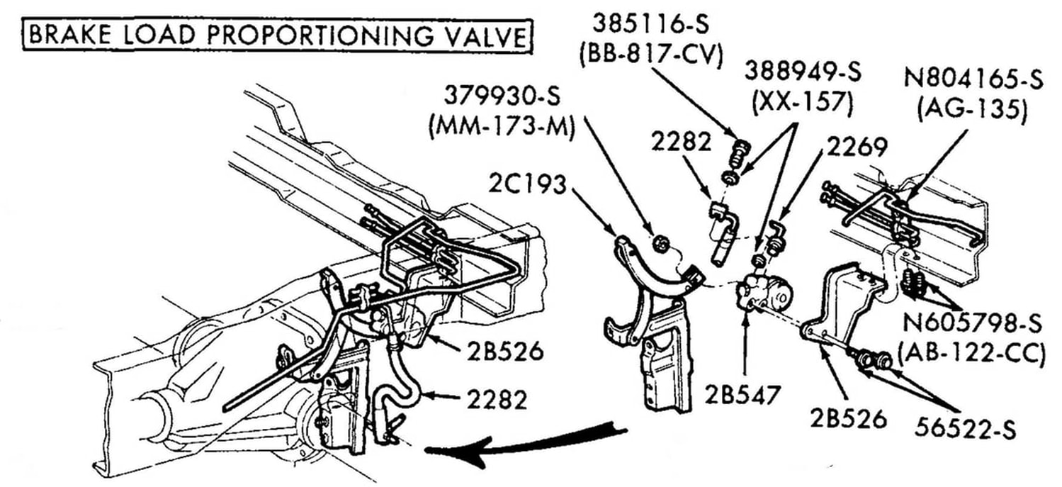
- There were two types of "proportioning valves" used in the Bullnose trucks - the Brake Pressure Differential Valve, which was used on all of the trucks, and the Brake Load Sensor Proportioning valve which was an additional unit used on the F250 and 350 trucks.
Ford's 1980 factory shop manual says this on Page 12-01-2 about the Brake Pressure Differential Valve:"The pressure, differential, proportioning and metering valve are three different systems. (Figs. 4 and 5). There are three functions of the pressure differential valve: It delays full effectiveness of the front brake, it proportions pressure to the rear system, and it operates a warning system in case of malfunction. During heavy brake application, the proportioning valve reduces pressure to the rear brakes to avoid lock-up. The metering valve delays effectiveness of the front disc brake until the rear brake shoes are against the drum."You can see the circuitry to the switch in the EVTM's, like on this page in the 1985 EVTM.
The other type of proportioning valve was the Brake Load Sensor Proportioning valve. It is positioned on the rear axle and has an arm that attaches to the frame. With a light load in the bed the valve limits the amount of hydraulic pressure sent to the rear brakes, but with a heavy load it allows full pressure to the rear brakes.
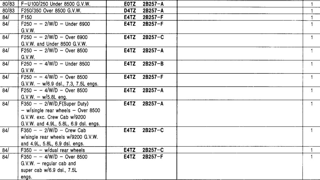
This valve was introduced on the 1984 F250's and as of 1985 used on both F250's and 350's. But in '84 there was only one valve for all GVW's, and then in '85 they came out with a different valve for each GVW.

