instrument cluster voltage regulator
Understanding Ford's 1980 - 86 Instrument Cluster Voltage Regulator, & replacing it for better gauge operation.
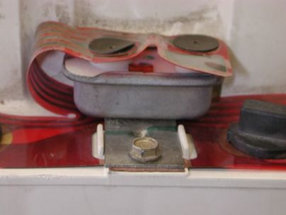
Ford's Instrument Cluster Voltage Regulator is anything but a voltage regulator. If you are a glutton for punishment there's a thread on FTE called ICVR Thoughts & Observations which explains, ad naseum, how they work. And, go here for the schematics for the instrument cluster.
Anyway, forgetting how they are supposed to work, what happens when they don't? Well, the three gauges the ICVR feeds (oil pressure, water temp, and fuel level) go wonky. Sometimes they don't work at all. Other times they work some of the time and then, in unison, go higher in the range. And other times they show much higher readings than they should. So, if you are chasing problems make sure to watch all three gauges. If they are working/not working together then the ICVR is the suspected culprit.
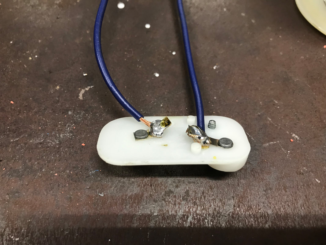
Ok, what does an ICVR look like, and where does it hide? The picture at the top of the page shows what it looks like in its natural habitat - the back of the instrument cluster:
So, now that we know where it hides, how do we replace it? Well, there are basically two options. You can find another one, maybe from a salvage, or you can replace it with a real voltage regulator to fix the problem once and for all. I like the latter solution as I don't like to worry about my gauges. In fact, since I've replaced the ICVR with a solid-state voltage regulator my gauges have never given me problems. But, I still run redundant mechanical gauges.
There are two ways to obtain a nice solid-state ICVR:
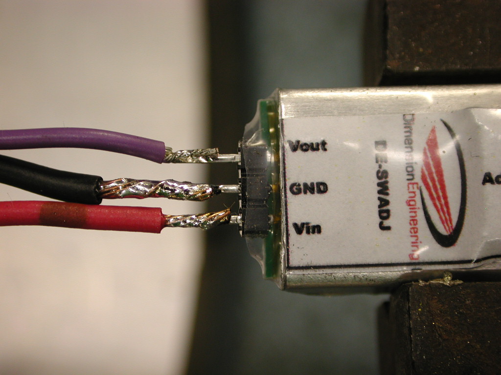
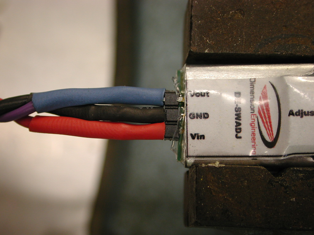
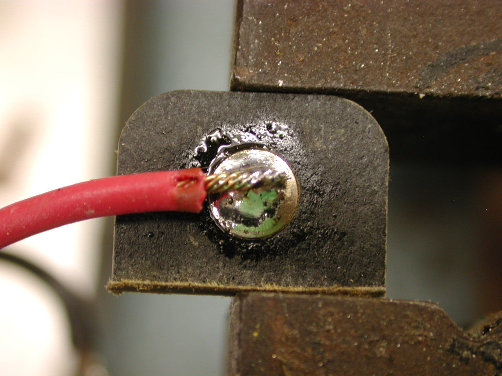
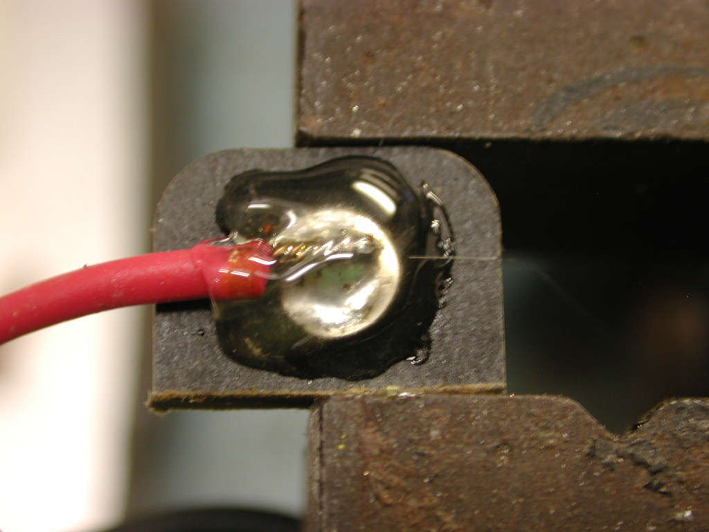
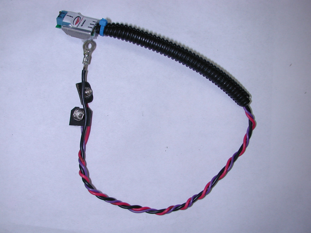
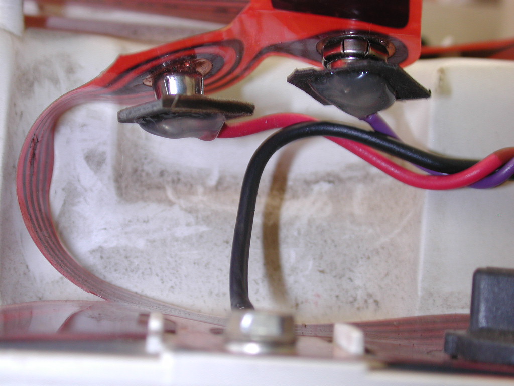
However, making your own isn't as simple as just buying the DE-SWADj3 regulator since it doesn't come ready to connect to the instrument cluster. You will need some wire, heat shrink tubing, a ring-tongue terminal, a 9-v battery terminal or an old ICVR, and a soldering pen. I used #16 wire, so small tubing to fit that is good. And the ring-tongue terminal should take that wire and accept a #8 screw - the one shown in the picture above. As for the 9v battery terminal or old ICVR, you need some way to connect to the terminals on the instrument circuit film. I used a 9 volt battery terminal, but Clayton Niedzielski pointed out that you can use an old ICVR by taking the shell and electrical parts off and soldering to the remaining terminals. I like his approach better than mine, but since most of the pics below show my approach I'll outline both.
As for a source for the 9 volt battery connector, Bentronics says they have it but I haven't purchased from them before so don't know anything about them. Or, you could do like I did and get one from an expired 9v battery, although it isn't always easy to solder to those connectors. But the battery terminal has to be cut apart so the terminals are separate since the ICVR's terminal spacing isn't the same as a 9v battery. The male battery terminal gets wired to the terminal on the regulator marked Vin. The female battery terminal gets wired to the terminal on the regulator marked Vout. And the ring-tongue terminal is wired to the terminal on the regulator marked GND.
There are two ways to obtain a nice solid-state ICVR:
- Buy: If you want to buy one, Dennis Carpenter appears to have a nice one that will plug right in.
- Make: If you want to make your own then I recommend buying a DE-SWADJ3 from Dimension Engineering.
However, making your own isn't as simple as just buying the DE-SWADj3 regulator since it doesn't come ready to connect to the instrument cluster. You will need some wire, heat shrink tubing, a ring-tongue terminal, a 9-v battery terminal or an old ICVR, and a soldering pen. I used #16 wire, so small tubing to fit that is good. And the ring-tongue terminal should take that wire and accept a #8 screw - the one shown in the picture above. As for the 9v battery terminal or old ICVR, you need some way to connect to the terminals on the instrument circuit film. I used a 9 volt battery terminal, but Clayton Niedzielski pointed out that you can use an old ICVR by taking the shell and electrical parts off and soldering to the remaining terminals. I like his approach better than mine, but since most of the pics below show my approach I'll outline both.
As for a source for the 9 volt battery connector, Bentronics says they have it but I haven't purchased from them before so don't know anything about them. Or, you could do like I did and get one from an expired 9v battery, although it isn't always easy to solder to those connectors. But the battery terminal has to be cut apart so the terminals are separate since the ICVR's terminal spacing isn't the same as a 9v battery. The male battery terminal gets wired to the terminal on the regulator marked Vin. The female battery terminal gets wired to the terminal on the regulator marked Vout. And the ring-tongue terminal is wired to the terminal on the regulator marked GND.
|
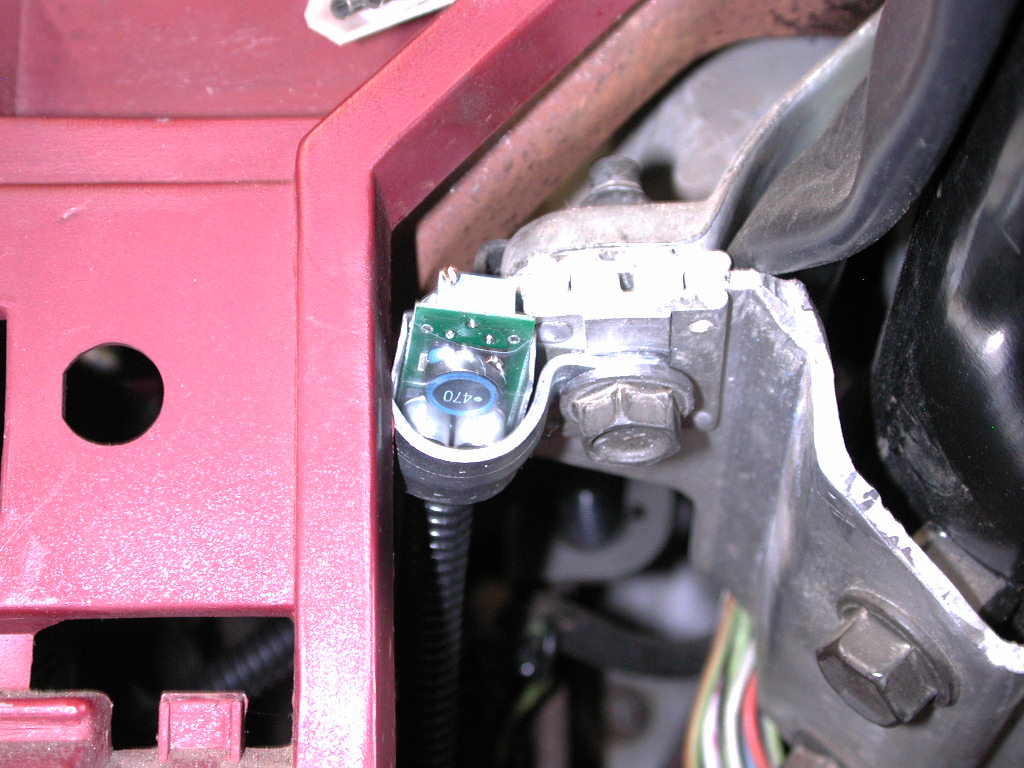
Now you need to hook it up to the instrument panel, as shown below. And then you'll need to dial in the voltage to 5.4 volts to calibrate the regulator. There's a screw on the end of the regulator that adjusts the voltage. Put the red lead of your meter on the female battery terminal and the black one on the ground wire at the screw, turn the key on, and quickly turn the screw to dial the voltage down to 5.4 volts. |
|
And, you just need to find some place to stash the regulator itself. I used a clamp and put it against the metal of the steering column clamp for a heat sink. But, I was using the 1 amp unit and if you are using the 3 amp unit there's no need to worry about having a heat sink. Just use a wire tie and secure it to something behind the instrument panel. |
That's all there is to it. Now you should have reliable gauges and you've peeled one more layer on the onion. Happy motoring!

