ignition
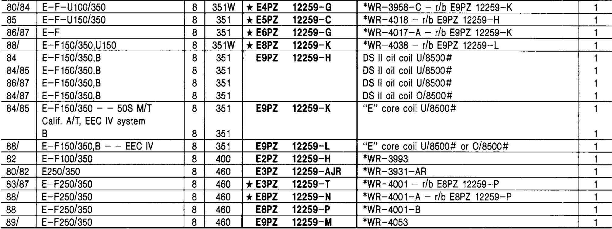
Part #'s for ignition modules, switches, & wiring, a wiring diagram for a one-wire distributor, like an HEI or DUI, & installation instructions for the switch.
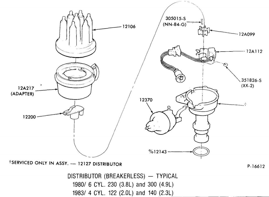
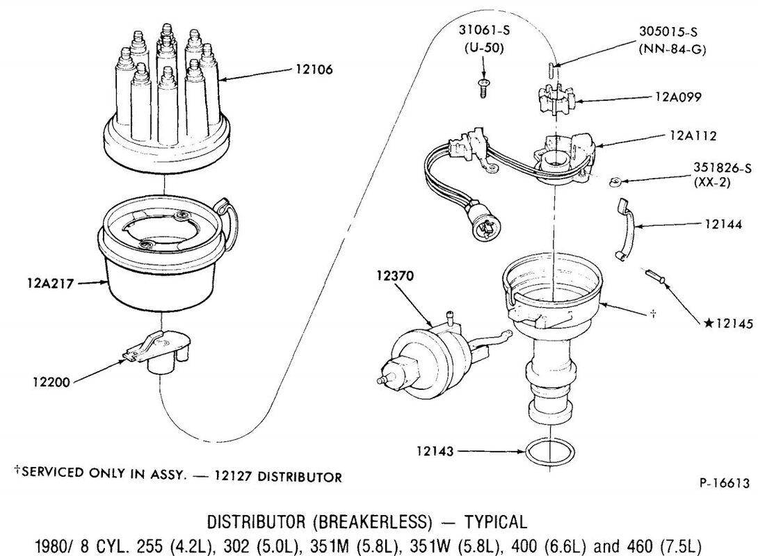
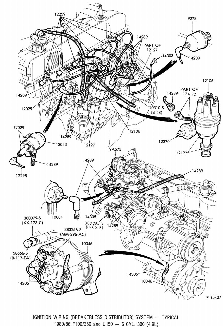
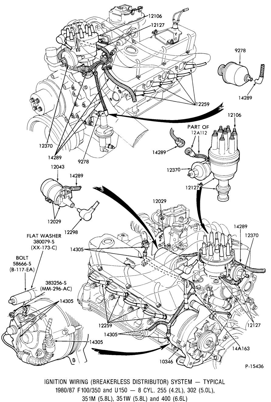
The Factory Shop Manual tab below provides information on how the ignition systems work, how to test them, and how to repair them. The Crane Cams tab provides information on what the different timing mechanisms do & how to modify them to re-curve a distributor.
In addition, Scotty Johnson, The Mad Porter, has instructions on his web site for re-curving a distributor: Page 1 & Page 2. (Yes, I know you can get to Page 2 from Page 1, but it isn't obvious.)
In addition, Scotty Johnson, The Mad Porter, has instructions on his web site for re-curving a distributor: Page 1 & Page 2. (Yes, I know you can get to Page 2 from Page 1, but it isn't obvious.)
This document is from the 1980 factory shop manual section on Engine Diagnosis & Service:
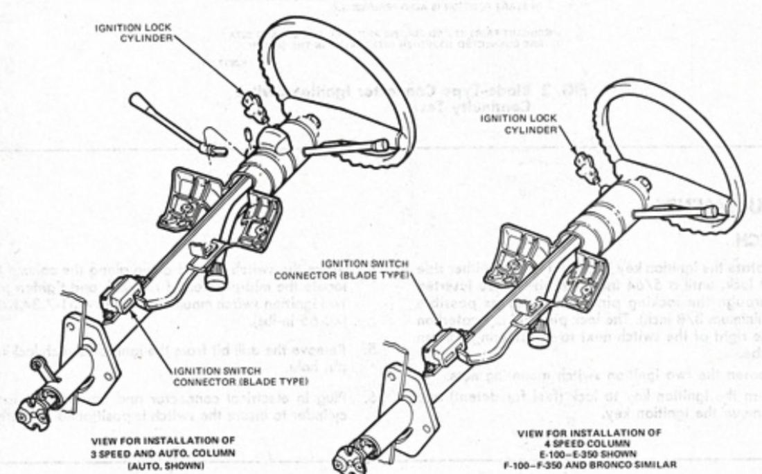
The ignition switch on these trucks can cause a number of problems. In fact, what most people think of as the switch, the thing into which you put the key, is actually just the ignition lock cylinder. The switch itself sits lower on the column, as shown in the illustration below.
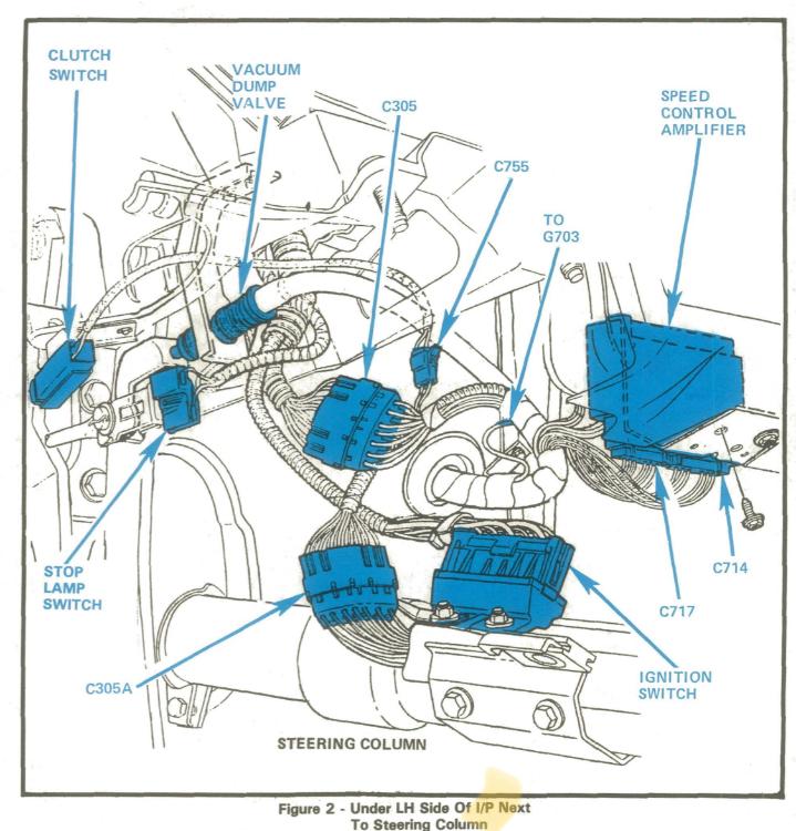
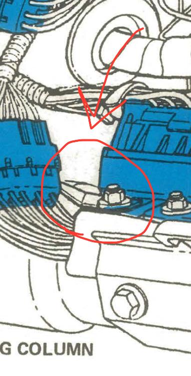
However, note that on some trucks there's a bracket that holds C305A under the nut holding the switch to the steering column. You can just see it in the center illustration, but the blow-up in the right illustration (thanks, Jeff) makes it easier to see.
However, note that on some trucks there's a bracket that holds C305A under the nut holding the switch to the steering column. You can just see it in the center illustration, but the blow-up in the right illustration (thanks, Jeff) makes it easier to see.
One of the problems trucks of this age frequently have with the switch is that the lubrication has set up and the key doesn't return from Start fully into Run. In this case the turn signals, clock, and several other items won't work properly, so this is a good tip off of the problem. This seems to happen most often when the weather gets cold and the lubrication sets up. If this is the case with your truck, try lubricating the lock cylinder and the link going to the switch. If that doesn't help then cleaning and lubricating the switch itself may be in order, and to do that a cleaner/lubricant like one made for TV tuners or radio controls works well.
Removal:
Installation:
Adjusting:
Lock Pin:
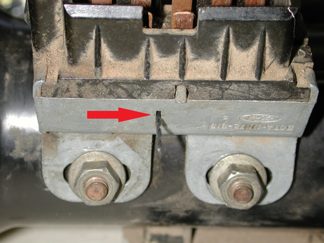
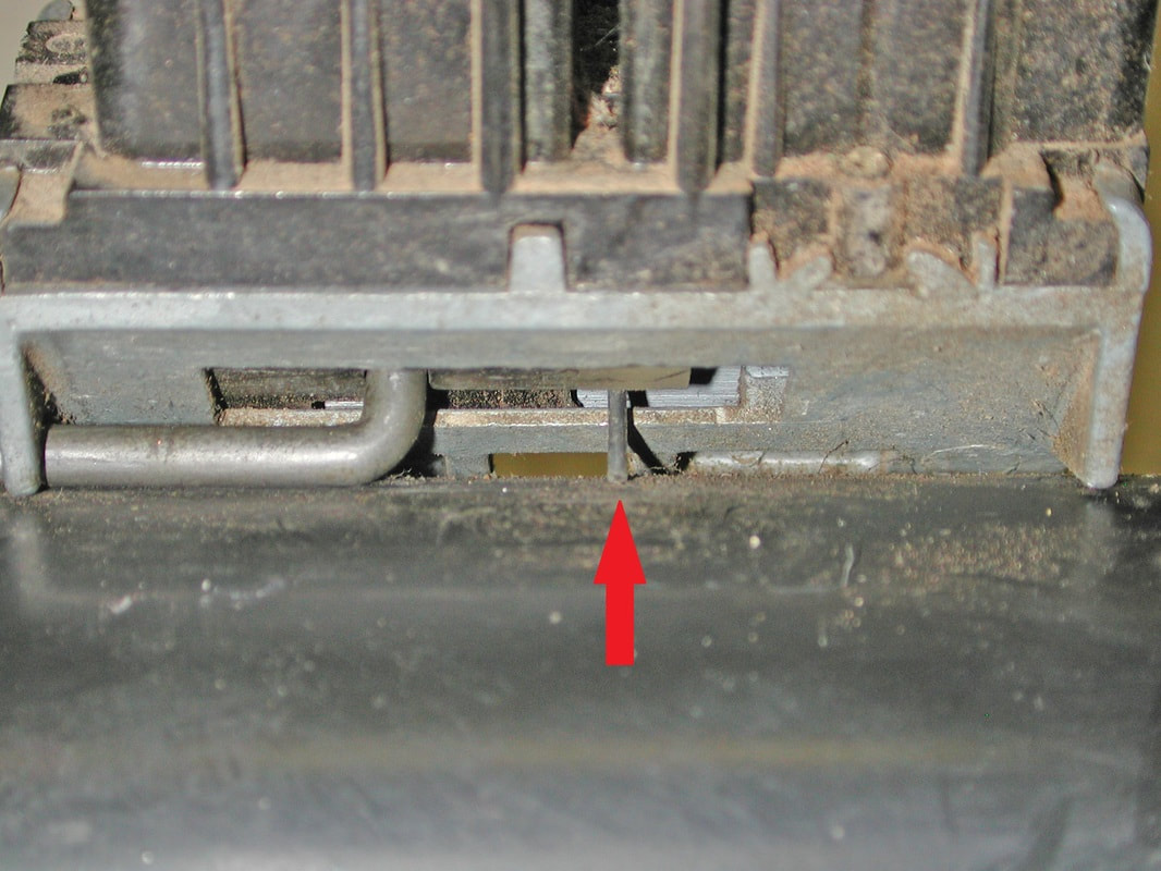
Put the lock pin (#56 or 3/64" drill bit) in from the left side of the switch, as shown below, and gently move the switch's internals up and down until the pin goes through the hole inside and comes out on the right side.
Removal:
- Disconnect the battery ground cable
- Remove the steering column shroud and lower the steering column
- Disconnect the switch wiring at the multiple plug
- Remove the two nuts that retain the switch to the steering column
- Lift the switch vertically upward to disengage the actuator rod from the switch and remove the switch.
Installation:
- When installing the ignition switch, both the locking mechanism at the top of the column and the switch itself must be in LOCK position for correct adjustment. To hold the mechanical parts of the column in LOCK position, move the shift lever into PARK (with automatic transmissions) or REVERSE (with manual transmissions), turn the key to LOCK position, and remove the key. New replacement switches, when received, are already pinned in LOCK position by a metal shipping pin inserted in the locking hole on the side of the switch. To insert a pin in a used switch refer to Adjusting.
- Engage the actuator rod in the switch.
- Position the switch on the column and install the retaining nuts, but do not tighten them.
- Move the switch up and down along the column to locate the mid-position of rod lash, and then tighten the retaining nuts.
- Remove the locking pin, connect the battery cable, and check for proper start in PARK or NEUTRAL. Also check to make certain that the start circuit cannot be actuated in the DRIVE and REVERSE position.
- Raise the steering column into position at the instrument panel (Part 13-06). Install steering column shroud.
Adjusting:
- Rotate the ignition key back and forth to either side of lock, until a #56 (.0465") drill bit can be inserted through the locking pin hole as far as possible (minimum 3/8"). (Note: I found that a .053" sewing needle is a perfect fit.) The lock pin hole is located on the right of the switch next to the steering column tube. See instructions and pictures, below.
- Loosen the two ignition switch mounting nuts.
- Turn the ignition key to lock (feel for detent) and remove the ignition key.
- Move the switch up and down along the column to locate the mid-position of rod lash and tighten the two ignition switch mounting nuts to 4.51-7.34 Nm (40-65 in-lbs).
- Remove the drill bit from the ignition switch locking pin hole.
- Plug in the electrical connector and operate the lock cylinder to ensure the switch is properly positioned.
Lock Pin:
Put the lock pin (#56 or 3/64" drill bit) in from the left side of the switch, as shown below, and gently move the switch's internals up and down until the pin goes through the hole inside and comes out on the right side.
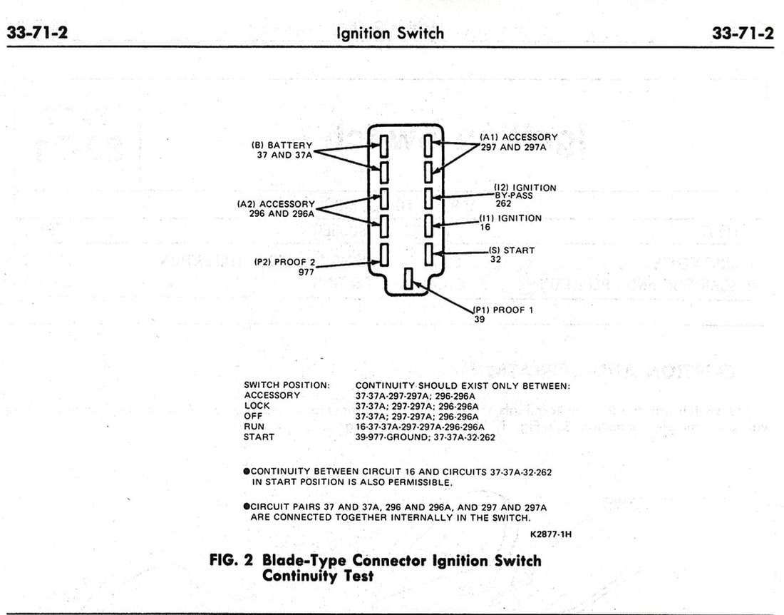
And, if you are testing an ignition switch, here are the pin-outs and continuity tests:
Finally, here are the part #'s. Note that the original switches for some trucks were marked E0TA-11572-B1B, but those were replaced by ones marked E4TA-11572-A.
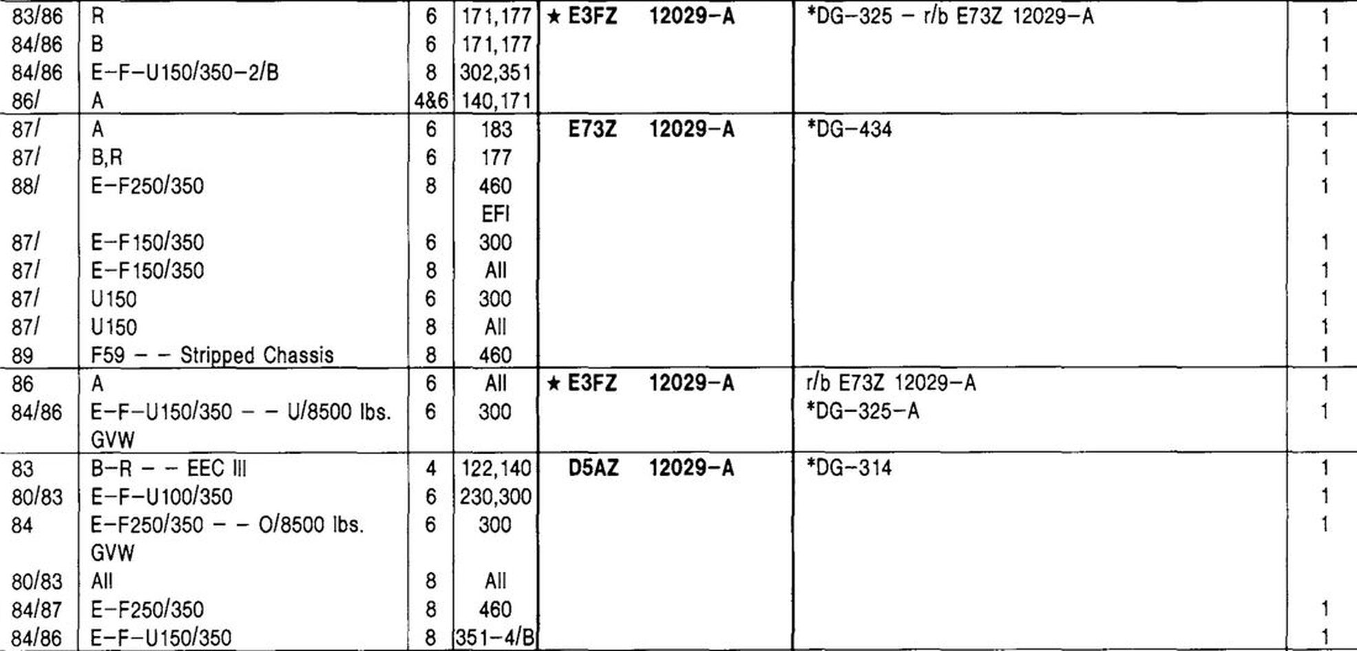
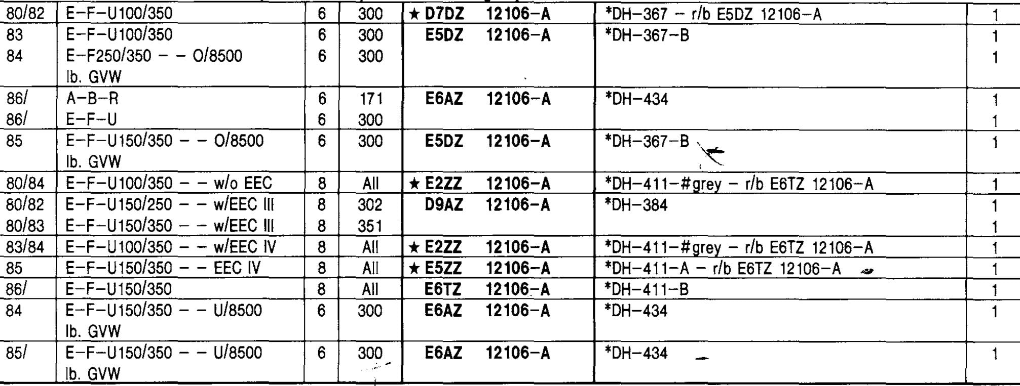
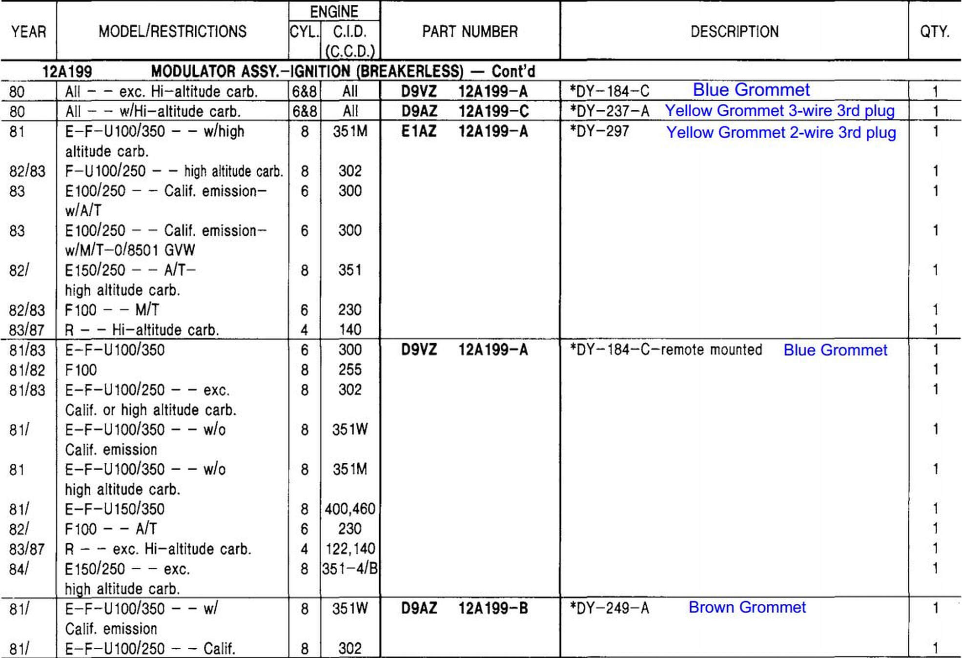
Listings of the ignition modules used on the 1980 - 86 Ford trucks. The information on the grommet colors was gleaned from Bob's Garage Library and BZEROB.com.
My understanding is the blue-grommet module was used without a computer, the EEC-III computer systems used the brown-grommet module, and the EEC-IV computer systems used the yellow-grommet modules with the 2-wire 3rd plug. I do not know with which computer system the 3-wire 3rd-plug yellow-grommet modules were used, but if you do please edify me.
My understanding is the blue-grommet module was used without a computer, the EEC-III computer systems used the brown-grommet module, and the EEC-IV computer systems used the yellow-grommet modules with the 2-wire 3rd plug. I do not know with which computer system the 3-wire 3rd-plug yellow-grommet modules were used, but if you do please edify me.
Many people are wanting to convert their trucks from Ford's EEC-III or IV ignition system to something that doesn't require a computer. Basically there are two ways to do that - either convert to a DS-II ignition system or install a one-wire distributor, sometimes called an HEI or DUI. The tabs below flesh out how to do either of those approaches.
But first, let's think through the advantages and disadvantages to either approach:
But first, let's think through the advantages and disadvantages to either approach:
- DS-II
- Advantages:
- Common: With the exception of the wiring harness (see below), all of the parts are readily available at a parts store or salvage, so if it breaks in the back-of-beyond you can easily get back on the road.
- Plug-And-Play: If you find all the parts it is plug-and-play.
- Disadvantages:
- Wire harness: These are becoming harder to find in usable form. And the aftermarket ones are fairly expensive and don't necessarily fit well.
- Wear: A used distributor can be badly worn. But, you can buy new DS-II distributors, and if that's done then this isn't a disadvantage.
- Advantages:
- One-Wire:
- Advantages:
- Advance curve: Many one-wire manufacturers dial in a curve for how you tell them the engine will be built.
- New: For the most part you'll be buying a new distributor
- Disadvantages:
- Rare: This is the flip-side of the DS-II in that you probably can't walk into any parts store and buy a replacement distributor should yours leave you on the side of the road.
- Wiring: As you'll see on the One-Wire tab, the wiring is fairly straightforward. However, you will have to do some wiring as there is no kit that I'm aware of that makes this a plug-and-play.
- Quality: There are good one-wire distributors and there are those that break quickly and frequently.
- Size: The HEI dizzy is much larger than the DS-II and that can cause problems with fitment.
- Advantages:
On the left below is the EEC wiring diagram from Ford's 1985 EVTM. While it is for the 4.9L engine, all of the EEC ignitions were wired the same way. The diagram shows the parts of the ignition system that you won't use if you are converting to a one-wire distributor. And on the right is an example of how you could wire your truck for a one wire dizzy. (Click on either to get a larger diagram.)
The relay shown is a common "Bosch" style relay like this one on Amazon. But, it is going to need some kind of weather protection to live under the hood. And, you will probably want to get a socket with pigtails to simplify the wiring, like this one on Amazon.
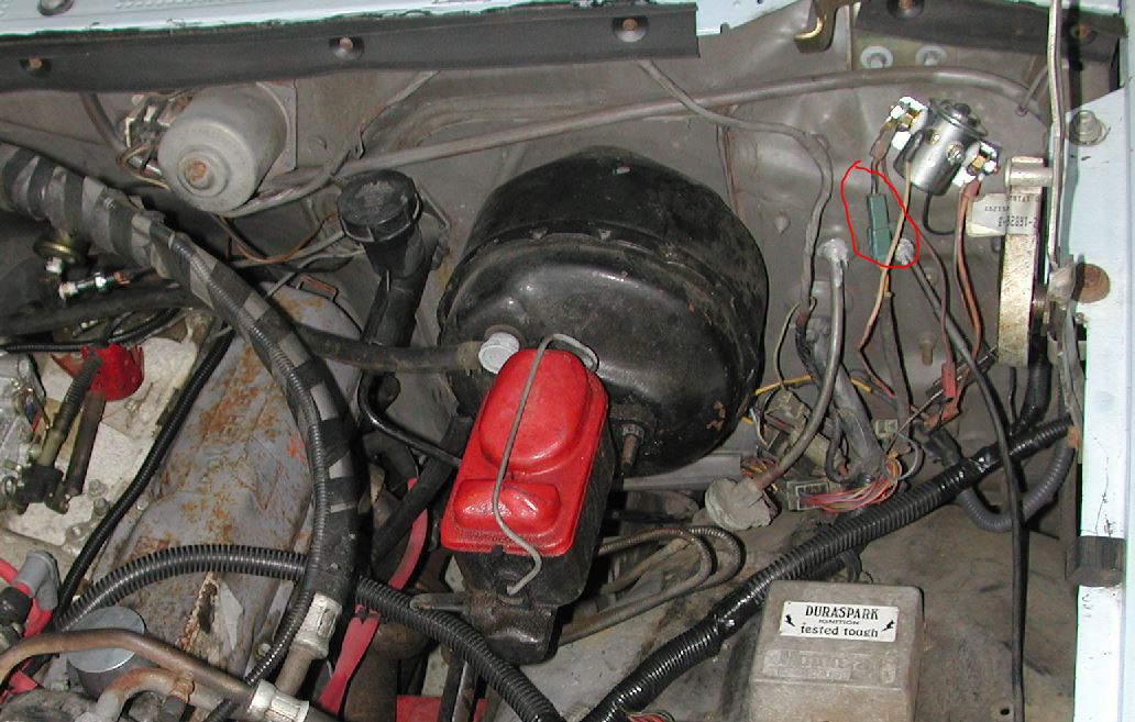
The pull-in voltage comes from the white/light blue wire that was previously connected to either the coil or connector C321. The power to a one-wire needs to be substantial since they require a lot of current, and should be at least a #12 wire. You can get that power from Circuit 37, which is a large yellow wire that is usually dead-ended below the brake master cylinder. If you have a factory auxiliary battery you'll have a relay on the firewall to the right of the master cylinder, and Circuit 37 will be connected to it, as shown below. Or, if you have the trailering option or a DRW truck you may have a power stud on the firewall with Circuit #37 connected to it. In any case you can connect to that circuit to get battery power for the ignition. However, you should put a fuse, probably a 20a one, in the circuit as that wire uses a fusible link that is capable of far more current than you need for the one-wire distributor.
The pull-in voltage comes from the white/light blue wire that was previously connected to either the coil or connector C321. The power to a one-wire needs to be substantial since they require a lot of current, and should be at least a #12 wire. You can get that power from Circuit 37, which is a large yellow wire that is usually dead-ended below the brake master cylinder. If you have a factory auxiliary battery you'll have a relay on the firewall to the right of the master cylinder, and Circuit 37 will be connected to it, as shown below. Or, if you have the trailering option or a DRW truck you may have a power stud on the firewall with Circuit #37 connected to it. In any case you can connect to that circuit to get battery power for the ignition. However, you should put a fuse, probably a 20a one, in the circuit as that wire uses a fusible link that is capable of far more current than you need for the one-wire distributor.
