motorcraft 2150
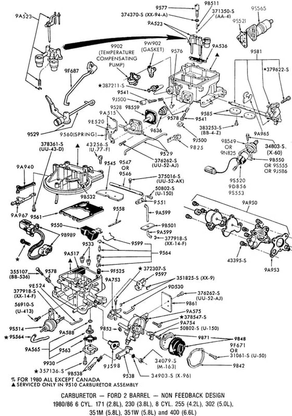
Theory of operation, internal and external system descriptions, part numbers and illustrations for Motorcraft's 2150 2bbl carburetors.
1980 - 86 FORD TRUCKS:
FUEL SYSTEMS
AIR CLEANERS
CARBURETORS, CHOKES, & EFI
CHOKES
CARTER YFA 1BBL
EFI
HOLLEY 4180C
MOTORCRAFT 2150
MOTORCRAFT 7200 VV
FUEL SYSTEM ILLUSTRATIONS
FUEL SYSTEM PART #'S
FUEL SYSTEMS
AIR CLEANERS
CARBURETORS, CHOKES, & EFI
CHOKES
CARTER YFA 1BBL
EFI
HOLLEY 4180C
MOTORCRAFT 2150
MOTORCRAFT 7200 VV
FUEL SYSTEM ILLUSTRATIONS
FUEL SYSTEM PART #'S
More information on these carbs can be found here:
And, heretofore I've linked to a web site called The Tek At Large where quite a bit of info was stored. Unfortunately he's discontinuing the site, but he has given me the right to publish his information here, as shown in the tabs below. Thanks, Rip!
- The 1985-1986 Fuel System Adjustments booklet
- Therangerstation.com's Motorcraft 2150/2100 Rebuild: A 47-page pdf on how to rebuild the 2100 and 2150 carbs
- Bubba's M-Block Ford Workshop: 2150 theory and operation, rebuilding tips, and performance & tuning
And, heretofore I've linked to a web site called The Tek At Large where quite a bit of info was stored. Unfortunately he's discontinuing the site, but he has given me the right to publish his information here, as shown in the tabs below. Thanks, Rip!
This section explains in detail how the Motorcraft 2150 2V carburetor works and it describes the major components and subsystems of the carburetor.
Even though a lot of people curse at their crusty old Motorcraft 2150s, the main problem always seems to be lack of maintenance and adjustment. Like all other carburetors, the Motorcraft 2150 needs occasional attention to keep it operating efficiently, and it needs tuning to get the best performance.
Among professionals, the Motorcraft 2150 is widely regarded as one of the best 2V carburetors ever made. It features an integral fuel bowl and main body, which eliminates the fuel leakage that some other carburetors are notorious for, and its booster venturi system uses “annular discharge” — the most efficient and effective system ever developed to atomize the fuel charge.
A stock Motorcraft 2150 is more tolerant of off-camber and steep angles than most other carburetors, modified or not. And a couple of simple modifications to the 2150 will improve its off-road capability substantially.
Fortunately, the Motorcraft 2150 carburetor is very easy to work on. Maintenance and basic tuning adjustments are simple. Even a novice can overhaul and rebuild a Motorcraft 2150 the first time with minimal skills. After just two rebuilds, you will be almost an expert.
Out-of-the-box, the Motorcraft 2150 is a good basic carburetor, though its performance potential is limited. In the hands of a skilled tuner, the Motorcraft 2150 can be adjusted to produce a very stable fuel/air ratio over a wide rpm range. With simple polishing and cleanup, it can be made to flow over 450 cfm, with excellent low-rpm throttle response and overall drivability. When set up correctly, the Motorcraft 2150 can be a superb low-end performance carburetor.
Carburetor basics
The purpose of a carburetor is to regulate the introduction of fuel into the intake airflow to produce the correct intake charge (fuel/air mixture) for combustion. If the carburetor works well, the engine can run powerfully and efficiently.
The Motorcraft 2150 carburetor uses two primary input signals to control fuel delivery functions:
- Throttle position
- Airflow velocity
Throttle position is controlled by the driver, using the accelerator pedal on a road vehicle. The accelerator pedal is connected to the throttle shaft by a lever on one end of the shaft and some combination of linkages and/or cables.
“Airflow velocity” refers to the speed at which air moves (or flows) through a conduit. In a carburetor, airflow velocity is important in the venturis' and in the throttle bores. The carburetor uses several “ports” (or holes) in the walls of the venturis' and throttle bores to acquire vacuum (i.e., pressure differential) signals related to the airflow velocity. Some of these signals are used by the carburetor to control the flow of fuel, and some are made available through ports on the outside of the carburetor to control other devices (such as ignition vacuum advance, EGR switching, etc).
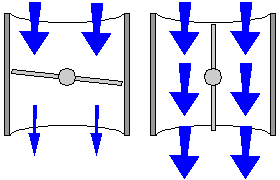
The orientation of the throttle plates determines the maximum airflow velocity through the carburetor. When the throttle plates are closed, airflow velocity is restricted to its minimum. When the throttle plates are wide open, airflow velocity can reach its maximum. The actual airflow velocity through the carburetor, however, is determined by both throttle plate orientation and engine speed.
In general, airflow velocity through the carburetor increases in proportion to engine speed, and the amount of fuel/air mixture metered into the engine increases with airflow velocity.
One more thing largely determined by throttle position is manifold vacuum. Manifold vacuum is the pressure differential between the air above the throttle plates and the air below the throttle plates. When the throttle position is wide open, manifold vacuum is at its minimum because there is little or no pressure differential between the air above and below the throttle plates. At any other throttle position, manifold vacuum increases as the throttle plates close, until it reaches its maximum when the throttle plates are completely closed.
Carburetor main assemblies
The Motorcraft 2150 2V carburetor consists of two main assemblies:
|
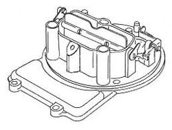
Air horn — the air horn is the carburetor’s main body cover. It contains the following components:
|
|
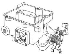
Main body (or throttle body) — the carburetor’s main body contains all the other components, including:
|
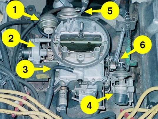
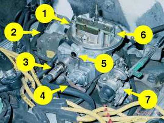
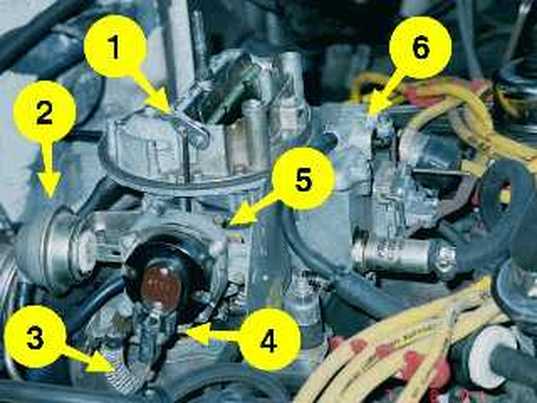
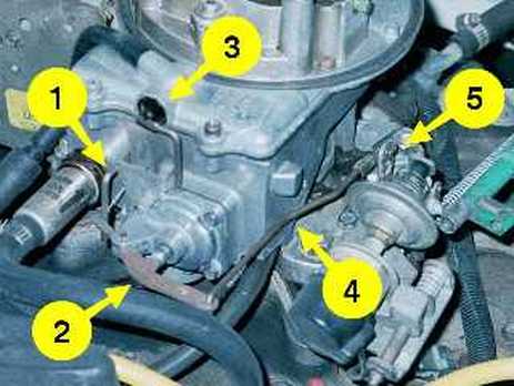
The following pictures point out some of the major features of the Motorcraft 2150 carburetor:
Once you understand some basics of how the carburetor works, you can contemplate your own performance tuning and enhancements.
To precisely regulate fuel delivery over a wide range of operating conditions, the Motorcraft 2150 uses several internal systems within the carburetor’s main body:
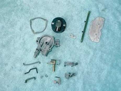
Some of the carburetor’s internal components are used by more than one fuel metering or control system. For example, the booster venturi assembly includes the main fuel well tube, the idle pickup tube, the main (anti-siphon) air bleeds, the high-speed air bleeds, the accelerator pump discharge nozzles, and the booster venturis with the main fuel discharge ports.
- Fuel inlet system — the float and needle valve that regulate fuel entering the fuel bowl.
- Idle system — the fuel metering system that controls the fuel/air mixture and fuel delivery at idle.
- Accelerator pump system — the system that delivers extra fuel immediately upon throttle movement to prevent a temporary fuel/air lean-out when the throttle plates open.
- High-speed bleed system and high-speed pullover system — two systems that regulate the fuel/air mixture to improve high-rpm performance, while allowing good low-rpm throttle response and drivability.
- Main metering system — the system that controls the fuel/air mixture under most open throttle conditions between idle and high airflow speed.
- Enrichment (power valve) system — a system that enriches the fuel/air mixture in response to lower manifold vacuum (created by open throttle plates).
Some of the carburetor’s internal components are used by more than one fuel metering or control system. For example, the booster venturi assembly includes the main fuel well tube, the idle pickup tube, the main (anti-siphon) air bleeds, the high-speed air bleeds, the accelerator pump discharge nozzles, and the booster venturis with the main fuel discharge ports.
|
Fuel inlet system:
When fuel enters the carburetor through the fuel inlet on the lower right front of the main body, it goes into the fuel bowl. The fuel bowl acts as a reservoir to hold sufficient fuel to accommodate any immediate demand for additional fuel. If fuel demand was constant, fuel could be supplied directly to the carburetor’s metering systems by the fuel pump, and there would be no need for a fuel bowl. |
The fuel inlet system uses a needle valve attached to a lever on a float to regulate the amount of fuel that enters the fuel bowl. The float moves up and down in response to the fuel level in the bowl. When the fuel level drops in the bowl, the float drops on one side of the pivot and raises the lever on the other side. The lever lifts the inlet needle off its seat to allow more fuel to enter the bowl. When the fuel level rises, the float rises and pushes the needle down onto its seat, cutting off the flow of fuel coming in from the pump.
The pressure produced by the fuel pump must be low enough to allow the float to close the needle valve (about 6-7 psi). If fuel pump output pressure is too high, it will force the needle valve open against the pressure exerted by the float and the carburetor will have flooding problems.
The main vents for the fuel bowl pass through the air horn, at the front corners of the choke tower. They are vented inside the air filter element in the air cleaner housing. Most mid-'70s (and later) carburetors also have a fuel bowl vent valve and/or vent tube on the front of the fuel bowl cover. The vent tube is connected to the evaporative emissions control system (EVAP) carbon canister.
Off-Road Tricks:
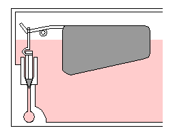
Some Motorcraft 2150 carburetors use a damper spring on the float pivot rod to stabilize the float when the vehicle is jostled.
Some early-'80s carburetors use a bowl filler that occupies the upper space to the left of the float (opposite the pivot rod). The bowl filler helps keep fuel from sloshing around excessively and helps maintain the fuel level above the power valve and main jets in the bottom of the fuel bowl. The float damper spring and bowl filler are both excellent modifications for an off-road carburetor.
|
Idle system:
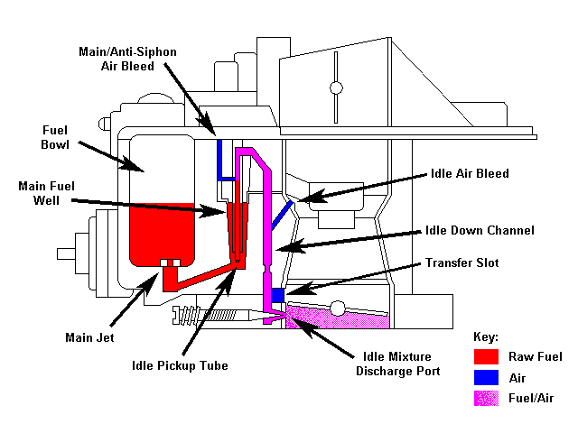
At idle, fuel is drawn into the throttle bores through the idle discharge ports, just below the closed throttle plates. The pressure differential between the fuel bowl and the throttle bores (i.e., manifold vacuum) causes the fuel to move. Fuel moves from the fuel bowl through the main jets, and into the main fuel wells. From the main fuel wells, fuel flows up the idle pickup tubes and through passages in the booster venturi assembly, then into the idle down channels in the main carburetor body. Calibrated openings at the bottom of the idle pickup tubes meter the flow of fuel into the idle system. |
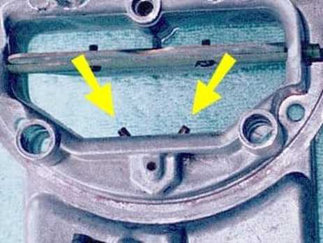
At off-idle, when the throttle plates begin to move, the transfer slots deliver fuel when exposed to the vacuum below the throttle plates. The transfer slots allow a smooth transition from the idle system to the main metering system as the throttle plates open.
As the throttle plates continue to open, airflow velocity increases through the main venturis and throttle bores, and the pressure differential in the booster venturis brings the main metering system into operation. As fuel begins to flow through the main metering system, it tapers off and stops flowing in the idle system.
As the throttle plates continue to open, airflow velocity increases through the main venturis and throttle bores, and the pressure differential in the booster venturis brings the main metering system into operation. As fuel begins to flow through the main metering system, it tapers off and stops flowing in the idle system.
|
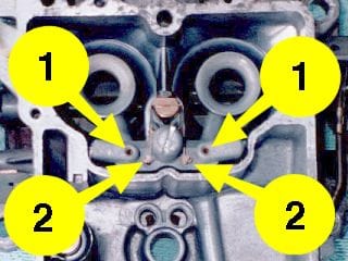
Air enters the idle system through the main (anti-siphon) air bleeds (1) and through the idle air bleeds (2) at the top of the main venturis. The idle fuel/air mixture moves through restrictors at the bottom of the idle down channels, and then mixes with more air drawn through the transfer slots just before passing through the idle discharge ports into the throttle bores. The amount of the idle fuel/air mixture that enters the throttle bores is controlled by the idle mixture adjusting screws. The tapered tips of the idle mixture screws protrude into the discharge ports and determine the effective metering area of the ports.
|
|
Some later model Motorcraft 2150 carburetors have a hot-idle compensator (HIC) valve mounted on the back of the air horn, behind the choke tower. The HIC system consists of a bimetallic strip attached an air valve, and special air passages inside the carburetor’s main body. When the temperature rises, the bimetallic strip opens the valve and allows air to enter the throttle bores under the throttle plates, which leans out the idle mixture and raises the idle speed. Higher idle speed makes the water pump move more coolant through the radiator and makes the fan move more air, thus preventing overheating during extended periods of idling.
|
Most mid-to-late '70s Ford vehicles used a hot-idle compensation system that was independent of the carburetor. It consisted of a ported vacuum switch (PVS) that switched the vacuum signal for the distributor’s vacuum advance system between the normal carburetor spark port (i.e., ported vacuum) source and full manifold vacuum. The PVS uses coolant temperature to determine when to switch. When ignition timing is advanced by the higher manifold vacuum, idle speed increases.
Bottom Line: The fuel/air ratio produced by the idle system is determined by three things:
Since no fuel flows through the idle system at engine speeds above idle, the idle mixture adjustment screws have no affect on fuel/air ratio, except at idle.
Accelerator pump system:
When the throttle plates open for acceleration, airflow through the venturis and throttle bores responds almost immediately. However, because fuel is heavier (and more dense) than air, the fuel flow takes longer to respond to a change in throttle position. The accelerator pump system provides an instantaneous “shot” of extra fuel in the main venturis as the throttle plates open. This extra fuel prevents a severe lean-out in the fuel/air mixture that would otherwise occur.
The accelerator pump system is activated by rotation of the throttle shaft when the throttle plates open. A lever on the top of the throttle shaft (called the over-travel lever) pulls the accelerator pump rod, which pulls the accelerator pump lever on the pump housing. The accelerator pump lever pushes the pump diaphragm in, which pushes fuel into the pump discharge passages inside the carburetor. When the throttle closes, the accelerator pump rod moves the pump lever forward, releasing the force on the pump diaphragm.
Inside the accelerator pump housing, the pump diaphragm has a spring under it to push the diaphragm back out when the pump lever is released. A soft rubber-like (elastomer) valve allows fuel to be pulled into the pump’s fuel chamber when the diaphragm is pushed out, and keeps fuel from returning to the bowl when the diaphragm is pushed in.
Bottom Line: The fuel/air ratio produced by the idle system is determined by three things:
- The amount of air drawn through the main air bleeds, idle air bleeds, and transfer slots
- The amount of fuel drawn through the calibrated opening at the bottom of the idle pickup tube
- The amount of fuel/air mixture that flows past the idle mixture adjusting needles and through the idle discharge ports
Since no fuel flows through the idle system at engine speeds above idle, the idle mixture adjustment screws have no affect on fuel/air ratio, except at idle.
Accelerator pump system:
When the throttle plates open for acceleration, airflow through the venturis and throttle bores responds almost immediately. However, because fuel is heavier (and more dense) than air, the fuel flow takes longer to respond to a change in throttle position. The accelerator pump system provides an instantaneous “shot” of extra fuel in the main venturis as the throttle plates open. This extra fuel prevents a severe lean-out in the fuel/air mixture that would otherwise occur.
The accelerator pump system is activated by rotation of the throttle shaft when the throttle plates open. A lever on the top of the throttle shaft (called the over-travel lever) pulls the accelerator pump rod, which pulls the accelerator pump lever on the pump housing. The accelerator pump lever pushes the pump diaphragm in, which pushes fuel into the pump discharge passages inside the carburetor. When the throttle closes, the accelerator pump rod moves the pump lever forward, releasing the force on the pump diaphragm.
Inside the accelerator pump housing, the pump diaphragm has a spring under it to push the diaphragm back out when the pump lever is released. A soft rubber-like (elastomer) valve allows fuel to be pulled into the pump’s fuel chamber when the diaphragm is pushed out, and keeps fuel from returning to the bowl when the diaphragm is pushed in.
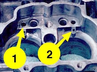
An air bleed orifice near the top of the accelerator pump fuel chamber prevents vapor pressure buildup under the pump diaphragm. When the diaphragm is pushed in, this orifice bleeds any vapor or air trapped under the diaphragm, as well as a metered amount of fuel, back into the fuel bowl. The size of this bleed orifice is a factor in determining the pump’s discharge volume. When the diaphragm pushes fuel into the pump discharge passages, the pressurized fuel pushes the pump discharge weight and check valve ball off their seat below the hollow screw in the middle of the booster venturi assembly. Finally, fuel is sprayed into both main venturis through the discharge nozzles on the booster venturi assembly.
|
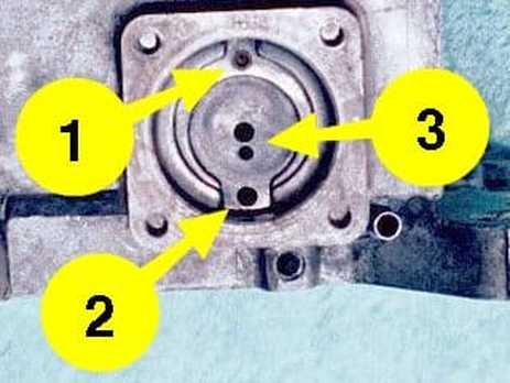
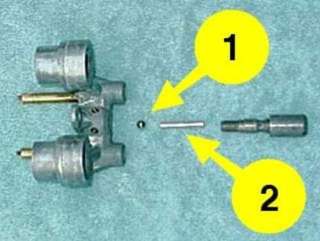
The purpose of the check valve ball and weight inside the hollow screw is to keep air from being sucked back into the discharge nozzles (and discharge passages) when the accelerator pump diaphragm is released. Since the diaphragm can’t pull air into the discharge passages, the negative pressure pulls fuel from the bowl, past the one-way elastomer valve, to refill the pump chamber so it’s ready for the next “shot.”
The volume of fuel and the rate at which it is discharged by the accelerator pump system is determined by several factors:
|
(1) Check valve ball and (2) check valve weight.
|
A poorly calibrated or improperly adjusted accelerator pump system can cause off-idle stumbling or hesitation, and weak throttle response.
High-speed bleed system:
Whenever the engine is running, the Motorcraft 2150 carburetor draws air into the main fuel wells through the main (anti-siphon) air bleed in the booster venturi assembly. The high-speed bleed system is designed to allow less air to be drawn into the fuel stream as the airflow velocity increases. This enriches the fuel/air mixture for high-rpm operation. There were two types of high-speed bleed systems used on Motorcraft 2150 carburetors:
In early 2150 models (mid-to-late 1970s), the main air bleed is integral with the high-speed air bleeds. In later 2150 models (early-to-mid 1980s), the booster venturi assembly has separate main air bleed and high-speed air bleed orifices.
The fixed high-speed bleed system uses fixed-orifice air bleeds in the booster venturi assembly. As fuel is drawn through the booster venturi discharge holes, air is drawn into the fuel stream through the bleed orifices, up to the airflow limit of the fixed orifices. The fuel/air mixture is enriched when the airflow velocity through the booster venturis increases beyond the point at which the fixed bleed orifices reach maximum flow.
With the fixed high-speed bleed system, the point at which enrichment begins is determined by the size of the fixed bleed orifices, and the rate of enrichment is determined by the rate of airflow velocity change.
High-speed bleed system:
Whenever the engine is running, the Motorcraft 2150 carburetor draws air into the main fuel wells through the main (anti-siphon) air bleed in the booster venturi assembly. The high-speed bleed system is designed to allow less air to be drawn into the fuel stream as the airflow velocity increases. This enriches the fuel/air mixture for high-rpm operation. There were two types of high-speed bleed systems used on Motorcraft 2150 carburetors:
- Fixed high-speed bleed system
- Variable high-speed bleed system
In early 2150 models (mid-to-late 1970s), the main air bleed is integral with the high-speed air bleeds. In later 2150 models (early-to-mid 1980s), the booster venturi assembly has separate main air bleed and high-speed air bleed orifices.
The fixed high-speed bleed system uses fixed-orifice air bleeds in the booster venturi assembly. As fuel is drawn through the booster venturi discharge holes, air is drawn into the fuel stream through the bleed orifices, up to the airflow limit of the fixed orifices. The fuel/air mixture is enriched when the airflow velocity through the booster venturis increases beyond the point at which the fixed bleed orifices reach maximum flow.
With the fixed high-speed bleed system, the point at which enrichment begins is determined by the size of the fixed bleed orifices, and the rate of enrichment is determined by the rate of airflow velocity change.
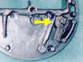
The variable high-speed bleed system consists of tapered metering rods that move up and down in high-speed air bleed holes to regulate the amount of air drawn into the main fuel well and the fuel stream flowing to the booster venturis. The metering rods are raised and lowered by a cam on the throttle shaft. When the throttle plates are closed, the cam does not contact the lift rod and the lift rod is held down by a spring. When the throttle plates open, the cam engages the lift rod, which raises the metering rods to close off the bleed holes and enrich the fuel/air mixture.
The variable high-speed bleed system provides more precise control of the fuel/air mixture over a wider range of engine speeds by linking mixture control directly with throttle position.
The variable high-speed bleed system provides more precise control of the fuel/air mixture over a wider range of engine speeds by linking mixture control directly with throttle position.
|
The high-speed pullover system consists of discharge nozzles in the front of the choke tower connected to a tube that extends from the carburetor main body cover down into the fuel bowl. Some Motorcraft 2150 carburetors also have an air bleed orifice between the discharge nozzles and the pullover tube. At high airflow velocity, the pressure differential created on the discharge nozzles in the choke tower draws fuel up from the bowl, through the pullover tube, to be released into the intake airstream. This enriches the fuel/air mixture for more high-speed power.
The fuel/air enrichment produced by the high-speed pullover system is determined by amount of fuel drawn through the calibrated opening at the bottom of the pullover tube, the size of the air bleed orifice (if used), and the size of the discharge nozzle openings. |
|
Main metering system:
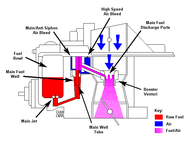
As airflow velocity increases through the venturis and throttle bores, it creates vacuum inside the booster venturis. Fuel is drawn through the main metering system by the pressure differential between the vacuum at the booster venturi main discharge ports and the air pressure inside the fuel bowl. Fuel is drawn through the main jet orifices at the bottom of the fuel bowl and into the main fuel wells. In the main fuel wells, it travels up the main well tubes and mixes with air drawn through the main (anti-siphon) air bleeds and the high-speed air bleeds. Air enters the fuel stream at the top of the main fuel wells through small holes in the main well tubes. |
As the throttle plates open further and airflow velocity increases, the high-speed air bleeds allow less air to enter the fuel stream, which enriches the fuel/air mixture to maintain the proper fuel/air ratio at high speed.
The main air bleeds are also called “anti-siphon” air bleeds because they act as a vent to prevent fuel from siphoning out of the fuel bowl and down into the idle system when the engine is not running. (Earlier model carburetors do not have separate main air bleed orifices; the high-speed air bleed orifices also function as main or anti-siphon air bleeds.)
The main metering system mixes fuel and air inside the carburetor, before it is introduced into the intake airflow. The fuel/air mixture in the carburetor is lighter than raw fuel, and thus it allows the carburetor to respond more quickly to changes in airflow or vacuum signals. When introduced into the intake airflow, the fuel/air mixture produced inside the carburetor atomizes more readily than raw fuel would.
In the main metering system, the final fuel/air ratio of the intake charge is determined by three factors:
Of these three factors, the one with the most impact on fuel/air ratio is the size of the main jet orifices. Fortunately, that one is also the easiest to change.
The main air bleeds are also called “anti-siphon” air bleeds because they act as a vent to prevent fuel from siphoning out of the fuel bowl and down into the idle system when the engine is not running. (Earlier model carburetors do not have separate main air bleed orifices; the high-speed air bleed orifices also function as main or anti-siphon air bleeds.)
The main metering system mixes fuel and air inside the carburetor, before it is introduced into the intake airflow. The fuel/air mixture in the carburetor is lighter than raw fuel, and thus it allows the carburetor to respond more quickly to changes in airflow or vacuum signals. When introduced into the intake airflow, the fuel/air mixture produced inside the carburetor atomizes more readily than raw fuel would.
In the main metering system, the final fuel/air ratio of the intake charge is determined by three factors:
- The amount of air drawn through the main air bleeds (if separate from high-speed air bleeds)
- The amount of air drawn through the high-speed air bleeds
- The amount of fuel drawn through the main jet orifices
Of these three factors, the one with the most impact on fuel/air ratio is the size of the main jet orifices. Fortunately, that one is also the easiest to change.
Enrichment system:
When engine load increases (such as climbing an increasing grade on a hill), and during high-speed operation, the fuel/air mixture must be enriched to increase engine power. The enrichment system supplies additional fuel to meet that demand.
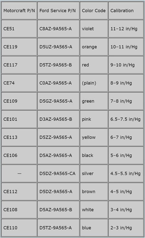
The enrichment system responds to changes in manifold vacuum. The enrichment system uses an enrichment valve (commonly called a “power valve”) to open an additional fuel metering path from the fuel bowl to the main fuel wells when manifold vacuum drops below a calibrated threshold.
High manifold vacuum (such as at idle or low load, part-throttle operation) pulls the power valve diaphragm against an internal spring and closes the valve so that no fuel can flow through it. At low manifold vacuum (such as at high load or high-speed open throttle), the force of the spring overcomes the vacuum to open the power valve and provide additional fuel to the main fuel wells.
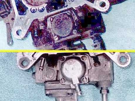
The power valve is installed on the bottom of the carburetor, with its valve opening in the bottom of the fuel bowl. When the power valve opens, it allows fuel to flow through restricted orifices in the carburetor main body, into the wells just below the main jets. From there, the fuel is drawn into the main fuel wells where it is added to the fuel drawn through the main jets to enrich the mixture produced by the main metering system. In effect, the power valve temporarily “enlarges” the main jet orifices.
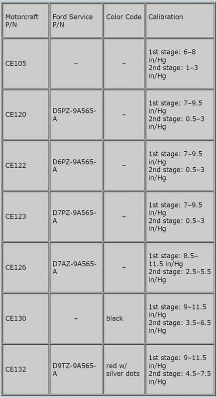
Some Motorcraft 2150 applications use a two-stage power valve. The two-stage valve works the same way as a single-stage valve, except that the first stage has a restricted fuel inlet. When the engine load causes manifold vacuum to drop below a second calibrated value, the second (unrestricted) stage of the valve opens.
Manifold vacuum is transmitted to the power valve diaphragm in one of two ways:
In the case of internal vacuum passages, the power valve cover is simply a closed chamber that seals the power valve diaphragm and the internal vacuum passage on the bottom of the carburetor.
The external vacuum nipple must be connected to a manifold vacuum source with a hose.
The power valve is installed on the bottom of the carburetor, with its valve opening in the bottom of the fuel bowl. When the power valve opens, it allows fuel to flow through restricted orifices in the carburetor main body, into the wells just below the main jets. From there, the fuel is drawn into the main fuel wells where it is added to the fuel drawn through the main jets to enrich the mixture produced by the main metering system. In effect, the power valve temporarily “enlarges” the main jet orifices.
Some Motorcraft 2150 applications use a two-stage power valve. The two-stage valve works the same way as a single-stage valve, except that the first stage has a restricted fuel inlet. When the engine load causes manifold vacuum to drop below a second calibrated value, the second (unrestricted) stage of the valve opens.
Manifold vacuum is transmitted to the power valve diaphragm in one of two ways:
- Through internal passages in the main body
- Through an external vacuum nipple on the power valve cover
In the case of internal vacuum passages, the power valve cover is simply a closed chamber that seals the power valve diaphragm and the internal vacuum passage on the bottom of the carburetor.
The external vacuum nipple must be connected to a manifold vacuum source with a hose.
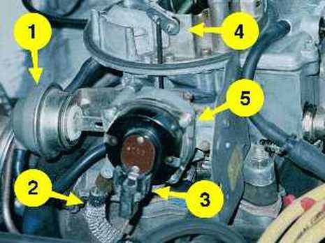
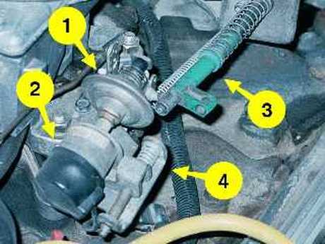
There are two “auxiliary” systems that are external on the Motorcraft 2150 carburetor: Automatic choke & throttle positioner.
Automatic choke systems
There were three automatic choke systems used on Motorcraft 2150 carburetors:
Both hot-air choke types use air tubes to get clean air from the back of the air horn (inside the air filter element) and pull it through a coiled heat exchanger tube mounted in the M-block’s intake manifold exhaust crossover passage.
Automatic choke systems
There were three automatic choke systems used on Motorcraft 2150 carburetors:
- Hot-air choke
- Hot-air choke with electric assist
- Electric choke
Both hot-air choke types use air tubes to get clean air from the back of the air horn (inside the air filter element) and pull it through a coiled heat exchanger tube mounted in the M-block’s intake manifold exhaust crossover passage.
The air picks up heat from the exhaust gas in the manifold crossover, then enters the coke housing where it warms the bimetallic thermostat before being pulled into the carburetor main body. When sufficient heat reaches the bimetallic thermostat, the choke opens.
Both the electric assist and all-electric chokes have an electric spade terminal on the end of the choke housing cap and one or more ceramic heaters inside the cap. The spade terminal is supplied with ~7v from the alternator’s stator terminal. Whenever the engine is running, the ceramic heater warms the bimetallic thermostat to open the choke.
To set (or load) the choke, you press the accelerator pedal all the way to the floor before cranking the engine. This allows the choke plate to be closed and the fast-idle cam to be set by the tension in the cold bimetallic thermostat.
Closing the choke plate temporarily enriches the fuel/air mixture to help start the engine in cold weather. Setting the fast-idle cam increases the engine’s idle speed to keep it running and help it warm up more quickly.
As the choke bimetallic thermostat warms up, it opens the choke plate and releases the fast idle cam so the engine can return to its normal idle speed when the throttle is cycled.
There are four choke adjustments you must make when you rebuild a Motorcraft 2150 carburetor:
- Choke cap position — this sets the degree of enrichment provided by the bimetallic thermostat in the choke housing cap.
- Pull-down clearance — the clearance between the choke plate and the inside of the choke tower when the pull-down diaphragm receives a vacuum.
- Fast-idle clearance adjusting cam screw — this synchronizes the fast-idle cam position with the choke-closed position of the bimetallic thermostat.
- Fast-idle adjustment screw — this sets the idle speed produced by the fast-idle cam.
Throttle positioner
There were four common types of throttle positioner used on Motorcraft 2150 carburetors:
A dashpot is a small air chamber with an internal diaphragm, a push rod, and a bleed orifice. As the throttle closes, such as under deceleration, the throttle lever contacts the push rod and applies force from the throttle return spring to the diaphragm, which pushes air out of the chamber through the bleed orifice to slowly allow the throttle to drop to its idle position. Dashpots were introduced as an emissions control device to reduce excess hydrocarbon (HC) emissions caused by over-rich fuel/air mixtures at closed throttle.
A vacuum kicker is a linear vacuum motor that uses a manifold vacuum signal to open the throttle plates slightly upon high-vacuum deceleration to reduce excess HC emissions.
Solenoids allow throttle position to be changed by an electric signal. They can be used with air conditioning (A/C) to increase the idle speed when the A/C compressor clutch engages. They can also be used as “anti-dieseling” devices, allowing the throttle plates to close farther than the curb idle position when the ignition is switched off.
With a solenoid throttle positioner, you set the curb idle with the solenoid in its “normal” position while the engine is running. In the case of an A/C solenoid, you set curb idle with the solenoid de-energized. In the case of an anti-dieseling solenoid, you set the curb idle with the solenoid energized. With a dashpot or vacuum kicker, you set the curb idle by turning the adjustment screw built into the back of the chamber.
There were four common types of throttle positioner used on Motorcraft 2150 carburetors:
- Dashpot
- Solenoid/dashpot combination
- Vacuum kicker
- Solenoid/vacuum kicker combination
A dashpot is a small air chamber with an internal diaphragm, a push rod, and a bleed orifice. As the throttle closes, such as under deceleration, the throttle lever contacts the push rod and applies force from the throttle return spring to the diaphragm, which pushes air out of the chamber through the bleed orifice to slowly allow the throttle to drop to its idle position. Dashpots were introduced as an emissions control device to reduce excess hydrocarbon (HC) emissions caused by over-rich fuel/air mixtures at closed throttle.
A vacuum kicker is a linear vacuum motor that uses a manifold vacuum signal to open the throttle plates slightly upon high-vacuum deceleration to reduce excess HC emissions.
Solenoids allow throttle position to be changed by an electric signal. They can be used with air conditioning (A/C) to increase the idle speed when the A/C compressor clutch engages. They can also be used as “anti-dieseling” devices, allowing the throttle plates to close farther than the curb idle position when the ignition is switched off.
With a solenoid throttle positioner, you set the curb idle with the solenoid in its “normal” position while the engine is running. In the case of an A/C solenoid, you set curb idle with the solenoid de-energized. In the case of an anti-dieseling solenoid, you set the curb idle with the solenoid energized. With a dashpot or vacuum kicker, you set the curb idle by turning the adjustment screw built into the back of the chamber.
Ford/Motorcraft 2150
By Bill Vose:
Early model 2100 carbs (pre-1964) had a long plunger on the pump diaphragm, and used a inlet check ball accessible through a special screw with a gasket under it. These also had a plastic filler block behind the diaphragm. On these carburetors the cone shaped spring goes small end in. All others go small end out.
When the 2150 was introduced, Ford went back to a plunger, most kits for these contain the diaphragm without the extended "stem" and have a short piece of round bar stock to extend the plunger.
On all 2100/2150 models the larger side center on the diaphragm goes out, small rivet head goes inside.
Other note, this carburetor was in production for a long time with very few changes to the basic design, in my shop we stocked 3 different brands of kits and all of them covered from 1958 (1957 was different enough to have a unique kit) till we sold it in 1978. As long as you know what year it came off, then you can get the settings. A partial number is stamped on the outside of the front left mounting ear. If you can't find a number, pick a vehicle with a similar engine and tell the parts store that, trust me it will work.
For those into performance, the left side of the bowl has a number cast into it, like 1.08, 1.14, or 1.33, these number represent the venturii size in inches, 1.33 was the biggest, and was used on 1970-71 429 engines, may have been on the 410 Mercury engines also.
- The Ford carburetors use a power valve that is essentially the same as the Holly ones. Ford uses a cover on the bottom of their carburetors, some applications use an external hose to the intake manifold.
- Accelerator pumps are a diaphragm style with an elastomer check valve for the inlet. After replacing it, the tip beyond the small ball needs to be trimmed off, otherwise it will hit the float and cause problems. The discharge check is a ball and there is a weight that is important, because it keeps the fuel from being pulled out of the discharge at full throttle. Many of them have adjustable stroke on the throttle shaft.
- The later 2150 carbs have a throttle operated pair of metering rods in the cluster that decrease the amount of air being bled into the main fuel circuits. This allows leaner main jets to be used yet still have a rich enough mixture at higher throttle openings. This yoke for the metering rods is not supposed to be adjusted as it will affect the emissions. If the yoke is raised, it will make the mixture richer from the point the cam on the throttle shaft starts lifting the yoke.
- Some of the later 2150s were feedback versions, and used an air bleed controller on the back of the carburetor, they also used an aneroid system for altitude compensation that mounted on the same location for high altitude models.
- Choke systems can be hot air, electric or a combination. The fast idle lever on the choke housing shaft is nylon and easy to break, older models had the lever retained by an E clip, later ones the lever is captured between two sides of the choke lever.
Early model 2100 carbs (pre-1964) had a long plunger on the pump diaphragm, and used a inlet check ball accessible through a special screw with a gasket under it. These also had a plastic filler block behind the diaphragm. On these carburetors the cone shaped spring goes small end in. All others go small end out.
When the 2150 was introduced, Ford went back to a plunger, most kits for these contain the diaphragm without the extended "stem" and have a short piece of round bar stock to extend the plunger.
On all 2100/2150 models the larger side center on the diaphragm goes out, small rivet head goes inside.
Other note, this carburetor was in production for a long time with very few changes to the basic design, in my shop we stocked 3 different brands of kits and all of them covered from 1958 (1957 was different enough to have a unique kit) till we sold it in 1978. As long as you know what year it came off, then you can get the settings. A partial number is stamped on the outside of the front left mounting ear. If you can't find a number, pick a vehicle with a similar engine and tell the parts store that, trust me it will work.
For those into performance, the left side of the bowl has a number cast into it, like 1.08, 1.14, or 1.33, these number represent the venturii size in inches, 1.33 was the biggest, and was used on 1970-71 429 engines, may have been on the 410 Mercury engines also.
How To Use This Document: To use this document you need a carburetor part number starting with 95.2, 95.3, or 95.3. If you don't have that then go to the page entitled CALIBRATION INFO & PART #'S to get it for your truck.
Let's assume that # is 95.2A. In that case your carb gets the parts called out with an "A" in column "A", below, and so on for B through M. But if it is 95.2N or after you'll have to scroll down and find the applicable page. And, don't miss that there's a 95.3, 95.4, and 95.7 down there.
Let's assume that # is 95.2A. In that case your carb gets the parts called out with an "A" in column "A", below, and so on for B through M. But if it is 95.2N or after you'll have to scroll down and find the applicable page. And, don't miss that there's a 95.3, 95.4, and 95.7 down there.

