electricity 099
A very basic discussion of Ohm's Law, the current draw of a circuit with or without poor connections, and how to calculate wattage.
|
Important variables: E is voltage; I is current; R is resistance; and W is power expressed in watts.
Important formulae:
|
I'm not qualified to teach Electricity 101, so this is just 099. But, I'm hoping to answer some questions that have come up on a thread in FTE called Dad's Alternator Dilemma. Basically those questions revolved around the problems experienced when poor connections are introduced into circuits. And poor connections can include switches which aren't up to the task and wiring that is too small, not just loose connectors.
There are essentially only three types of passive components in electrical circuits: resistors, capacitors, and inductors. Poor connections have little if any capacitance and no inductance, so fall into the resistance camp. Given that, what does increased resistance do to a circuit? It reduces the current flowing in the circuit and creates heat where the "poor connection" is. How do I know that? It is given by Ohm's Law, which is shown as E=IR. Or, if we solve for I we get I = E/R.
Conclusion: If the voltage doesn't change but the resistance goes up then the current goes down.
Example 1 - 1157 Bulb:
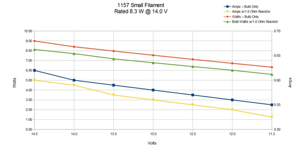
The first example is a simple 1157 bulb like is used in many stop/tail lights. The tail light filament on an 1157 is rated at 8.3 watts at 14.0 volts. Using the formula of Watts = voltage (E) times current (I) we find that the bulb should be pulling .59 amps at 14 volts to give 8.3 watts. So, I hooked an 1157 to my variable power supply and checked the current at every .5 volts from 14.5 down to 11.5. Sure enough, it pulled .6 amps at 14.0 volts. But, what happens if you introduce a "poor connection" into the circuit? I added a 1.6 ohm resistor and ran the test again. Now I got .59 amps at the same voltage. So, added resistance reduces the current in a lighting circuit. But, that also means less wattage from the bulb and, therefore, less light. Wattage is, as previously said, voltage times current. In my testing I got 8.40 watts from the bulb itself at 14.0 volts, and 8.26 watts with the resistor added to the circuit at the same voltage.
Here's a chart that shows what I found in my testing:
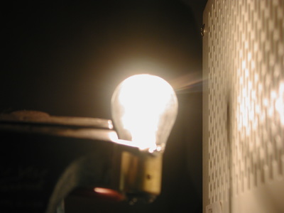
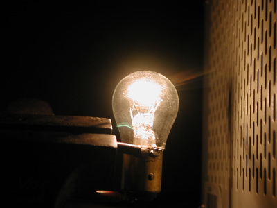
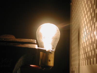
So, what difference can be seen on the bulb with the varying voltages and currents? That's an interesting question to answer because it requires a camera to capture the image, and cameras are usually set in a mode where they automatically adjust the lens &/or shutter speed to get the same brightness from scene to scene. In other words, if a camera is used in automatic mode the camera will adjust so that the bulb will look as bright regardless of the voltage and current. And, the pictures below show that as the one on the left was taken in Program mode with voltage at 14.5 volts and current at .62 amps, while the one on the right was taken in Program mode with voltage at 11.5 volts and current at .53 amps. The camera did a pretty good job as both shots are about the same brilliance. However, the shot in the middle was made with the camera on Manual mode and the shutter and aperture set to the same as the picture on the left, while the voltage and current were the same as the picture on the right - 11.5 v and .53 amps. And there you can see the reduced brilliance as well as the yellow coloring of the bulb.
Example 2 - Headlights:
As explained on the page for Headlight Wiring Harnesses, in my opinion the factory wiring on the 1980 - 86 Ford trucks, and almost all other vehicles at the time, was marginal at best. And, by this point in time it can easily cause a fire that will total your truck. Why? Because there are several "poor connections" in the system that were iffy originally and have only gotten worse. Further, these poor connections are making the headlights dim.
To prove this I tested my '81 F150, Rusty, with and without the headlight relays I've installed. Here are the results:
As you can see, the headlight relays and harness give essentially the same results as a bulb connected directly to the battery. But, the stock wiring on Rusty, which hasn't melted yet, is losing 17% of the wattage. On top of that, somewhere in the truck's wiring over 8 watts of power is being turned to heat. As it turns out, that's exactly what the small filament in an 1157 uses, and they get HOT. So, if all of that is being generated in one spot, like a bad connection or the switch itself, problems are soon to follow.
Example 3 - HVAC Blower:
Ok, those two tests were with incandescent lights, which are purely resistive loads. How about an inductive load? What happens when you introduce a resistance in that kind of a circuit? Well, it just so happens we have one that is easy to test in these trucks - the HVAC blower motor. On those all the switch does is to pick how much resistance to add to the circuit, with High/1 having no resistance, 2 having .9 ohms, 3 having 1.7 ohms, and Low/4 having 2.0 ohms. So, I tested that and got these results:
As you can see, I ran two tests - one with just the battery supplying current and one with a charger set on 10 amps. In both cases adding resistance to the circuit decreases the current draw of the motor. Also, note the "Calc'd" and "Measured" resistance #'s. The calculated #'s come from using Ohm's law and dividing the voltage by the current to get the resistance. The measured #'s come from using my DVM across the motor and the resistors. As you can see, the numbers for High and 2 are spot-on, but 3 and Low are off. I suspect that is because the resistors are getting hot in use and changing their resistance. And, we know for sure they get hot as they'll light up leaves and such that get packed in around them. My calculations show that #2 should see about 60 watts, #3 about 45, and #4 about 30. That's a lot of power, and easily explains the smoke or fire.
Now, does this also mean that a bad connection to a starter will reduce current? I think so, but I don't have empirical proof. However, that doesn't explain the problems many have experienced with solenoids welding shut or wires melting - unless the solenoid or the wire itself was the bad connection. It doesn't take much resistance at over 100 amps to make a lot of heat.
Now, does this also mean that a bad connection to a starter will reduce current? I think so, but I don't have empirical proof. However, that doesn't explain the problems many have experienced with solenoids welding shut or wires melting - unless the solenoid or the wire itself was the bad connection. It doesn't take much resistance at over 100 amps to make a lot of heat.


