speedometer gears, Cables, & Sensors
How to find the right gears to calibrate your speedometer.
One of the perennial questions is "What gears do I need to use to get the speedo to read correctly?" "It depends" is the best answer as there are several variables involved, including the rear tire size, or more correctly the tire's rolling diameter, the rear axle ratio, the speedometer drive gear, and the speedometer driven gear.
But the terms "drive gear" and "driven gear" are somewhat confusing, so here's are definitions:
Ok, now that you know what the variables are, how do you figure out what gears you should have in your setup to calibrate your speedometer? To solve those I offer the calculators shown on the Calculator tab.
But the terms "drive gear" and "driven gear" are somewhat confusing, so here's are definitions:
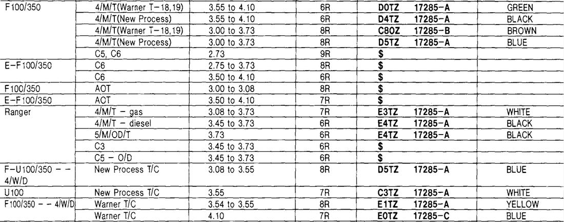
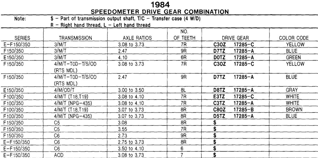
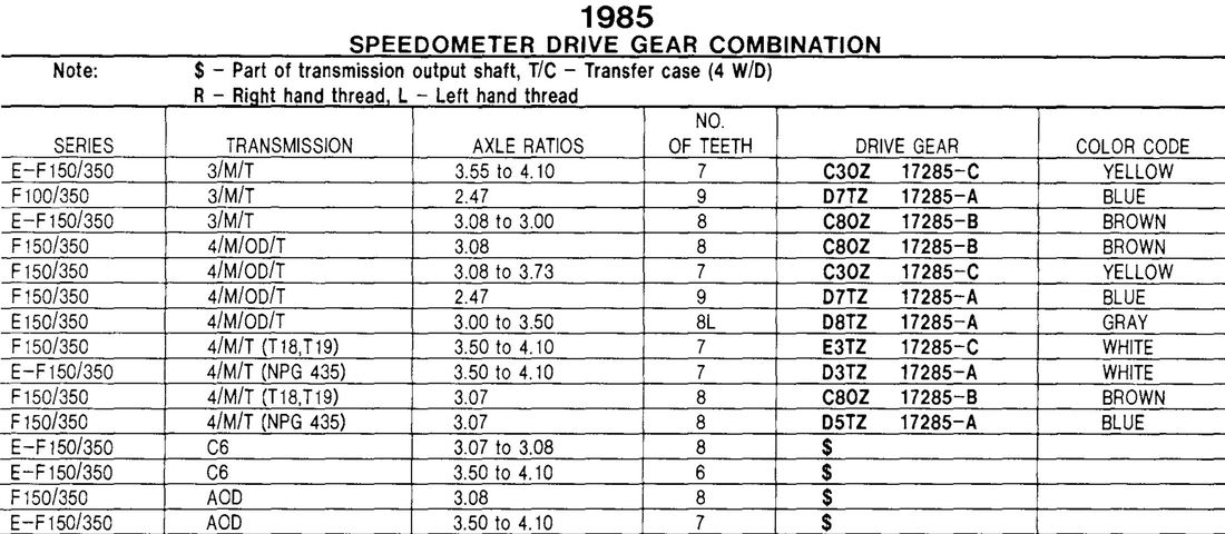
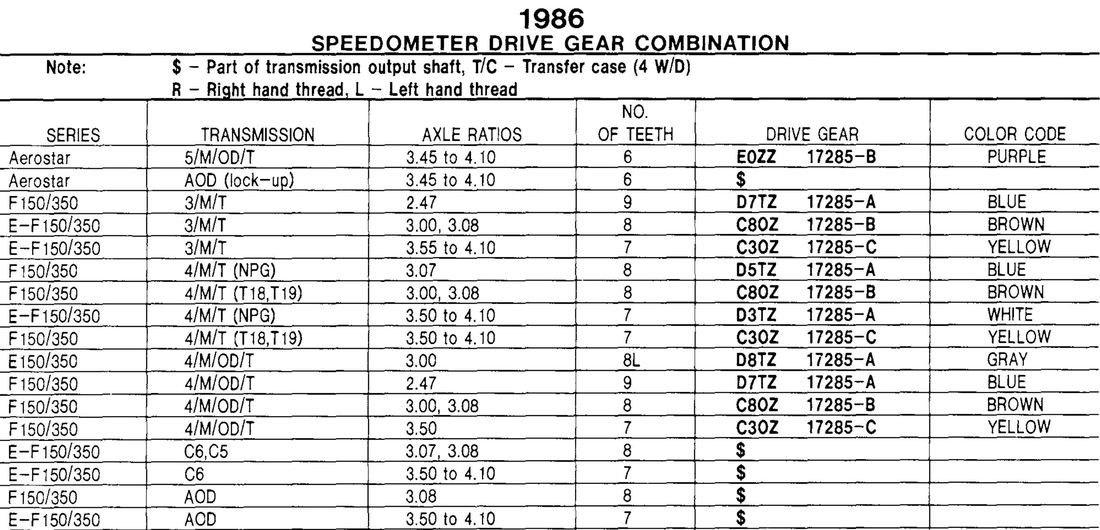
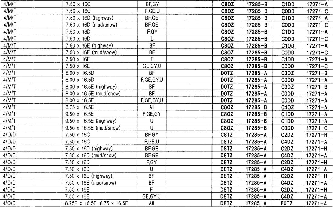
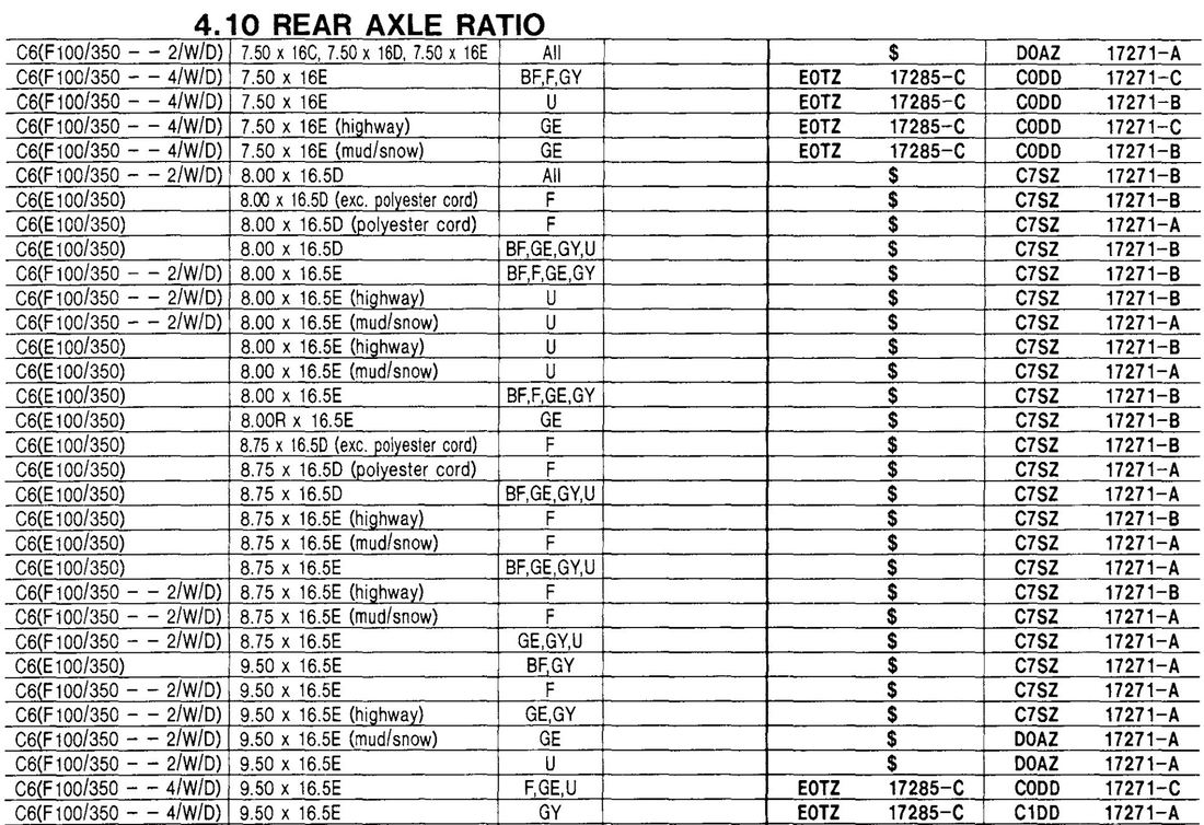
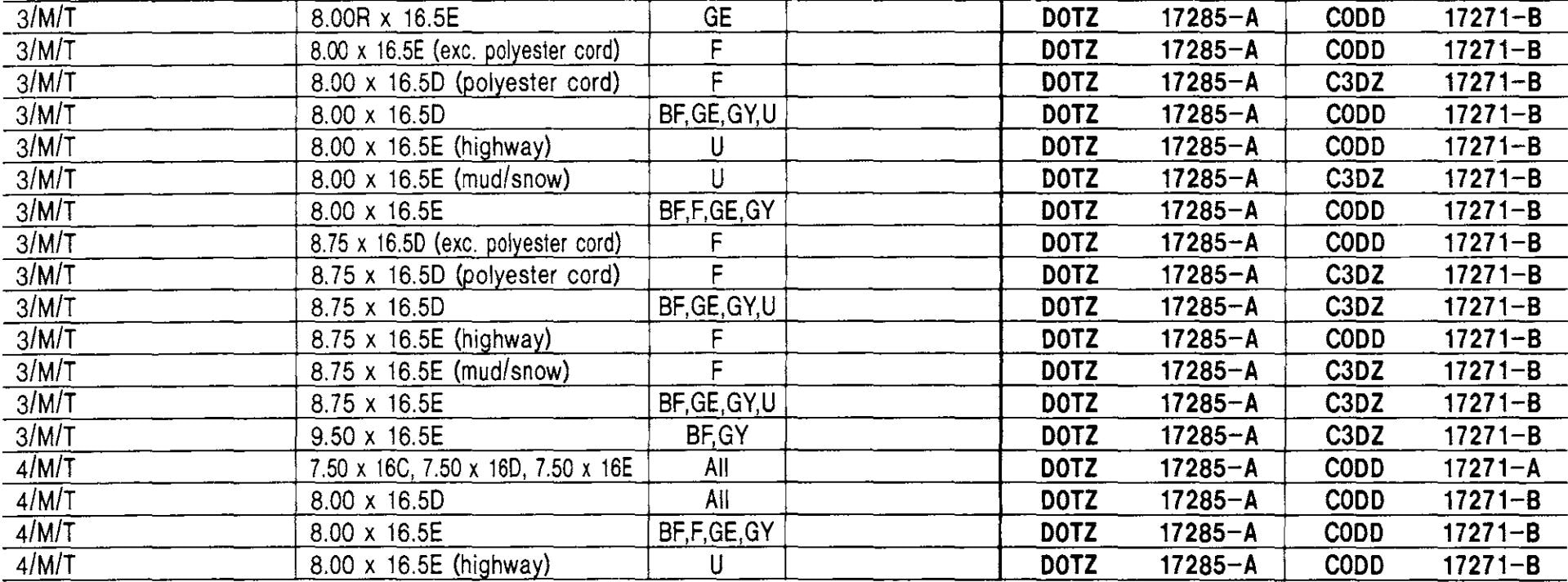
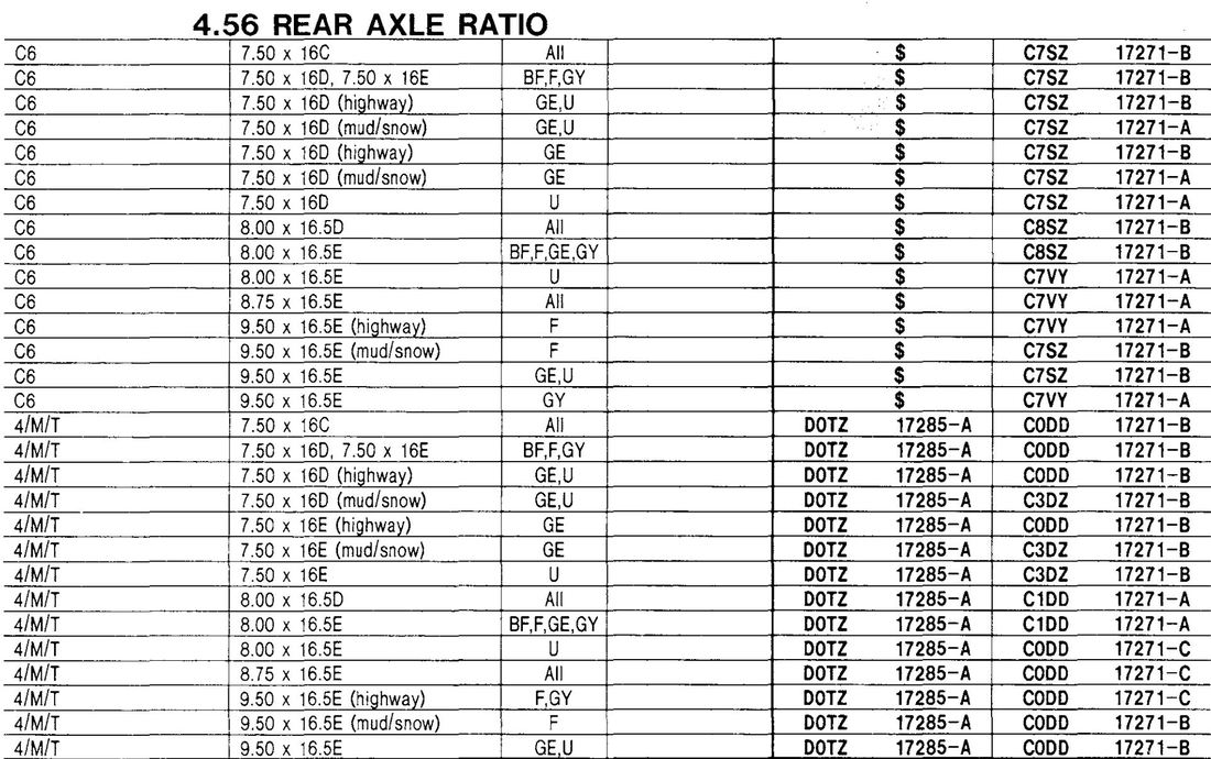
- Drive Gears: This is the gear that is on the output shaft of the transmission if the truck is a 2wd, or on the output shaft of the transfer case if it is a 4wd. The Drive Gear tab lists the drive gears used for each year, transmission or transfer case, and axle ratio. But, the Driven Gear tab also lists the drive gear in the tables, so you can look the drive gear up there as well.
- Driven Gears: This is the gear that is on the end of the speedometer cable that plugs into either the transmission or transfer case depending on if it is 2wd or 4wd. And the Driven Gear tab lists the driven gears used for each axle ratio, specific transmission, and tire size.
Ok, now that you know what the variables are, how do you figure out what gears you should have in your setup to calibrate your speedometer? To solve those I offer the calculators shown on the Calculator tab.
|
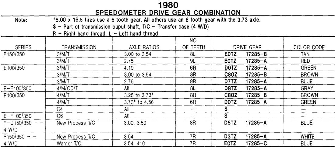
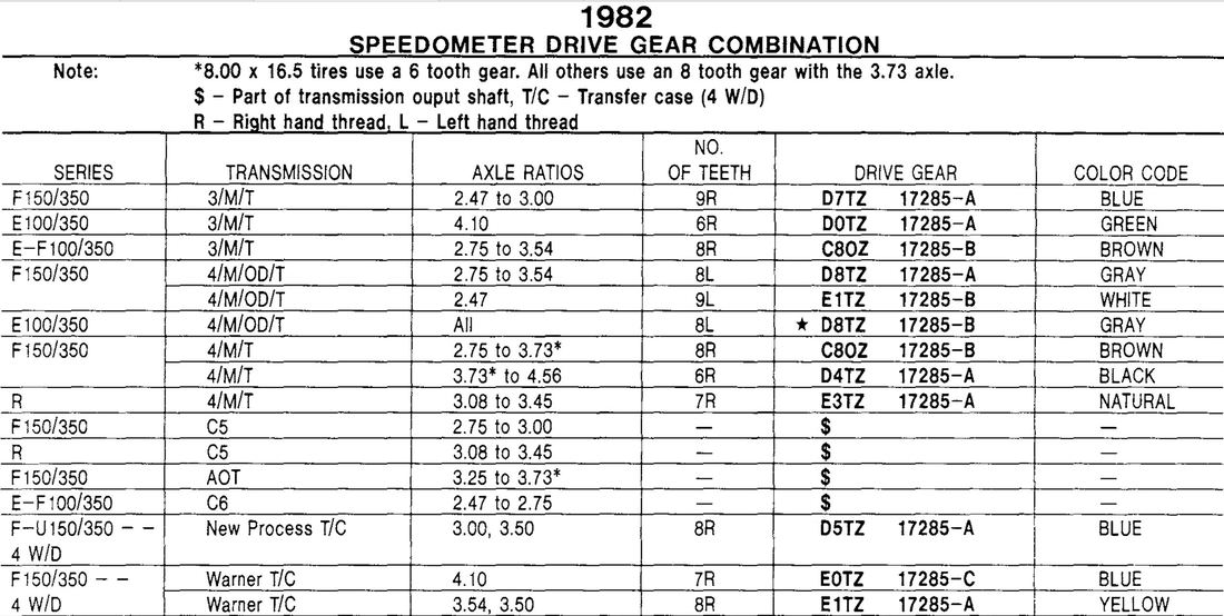
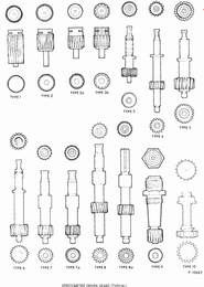
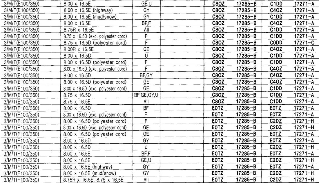
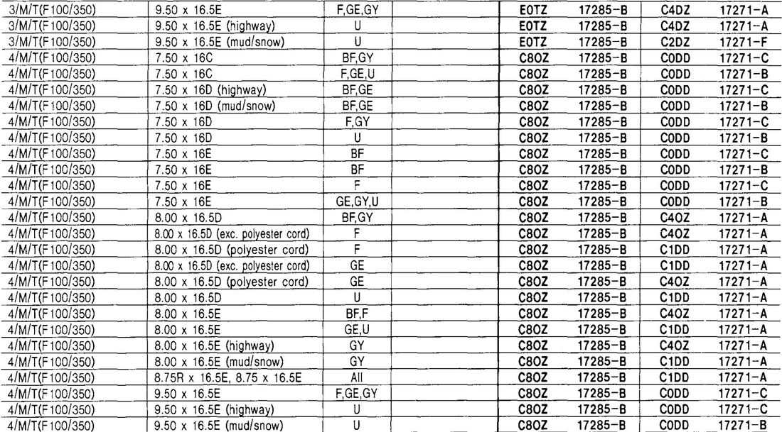
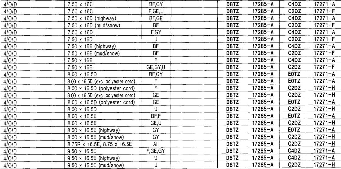
As said, the drive gear is the gear on the output shaft of the transmission or transfer case. Ford used 6, 7, and 8-toothed drive gears for the 1980 - 86 trucks, and the determination of which to use was based primarily on the rear axle ratio of the vehicle. However, there were apparently some other circumstances that changed things because according to the following tables the Broncos sometimes got a smaller driven gear than a pickup when using the same axle ratio.
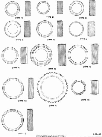
Anyway, the drive gears used on these trucks come in several "types", as shown to the right. (Click on the illustration to have it open larger.) |
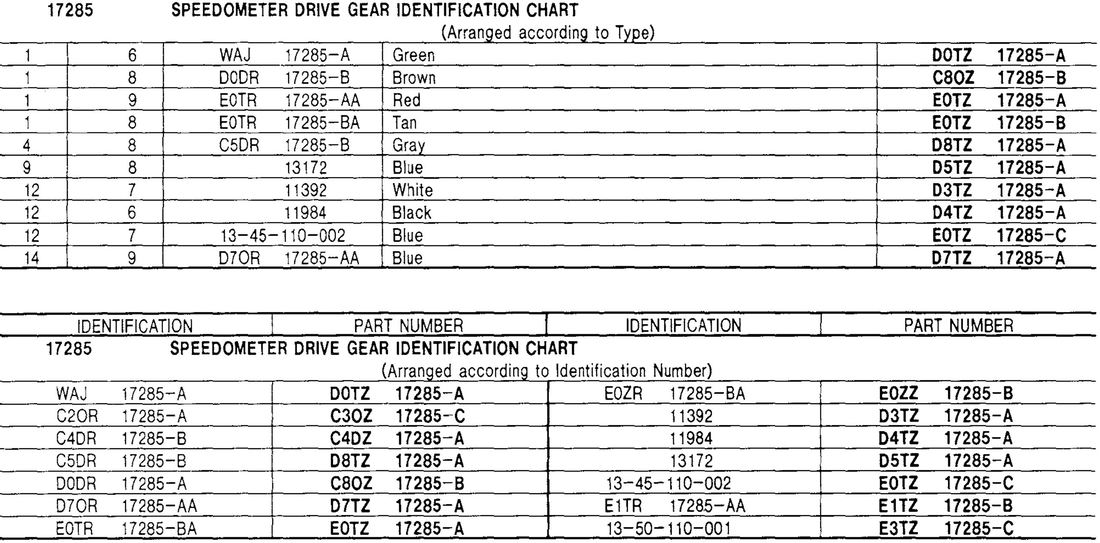
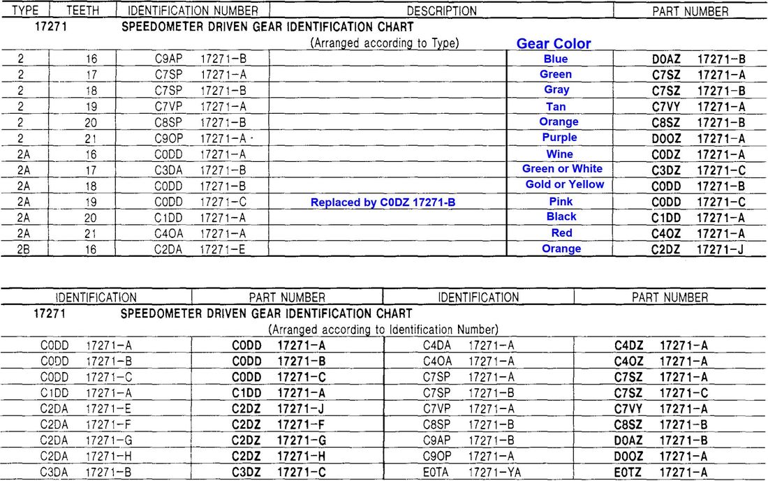
Here are two tables to let you figure out which part # goes with which type. Note that the first chart is by type, and the second chart is by ID number. And, note that the 2nd chart has two sets of columns.Here are two tables to let you figure out which part # goes with which type. Note that the first chart is by type, and the second chart is by ID number.
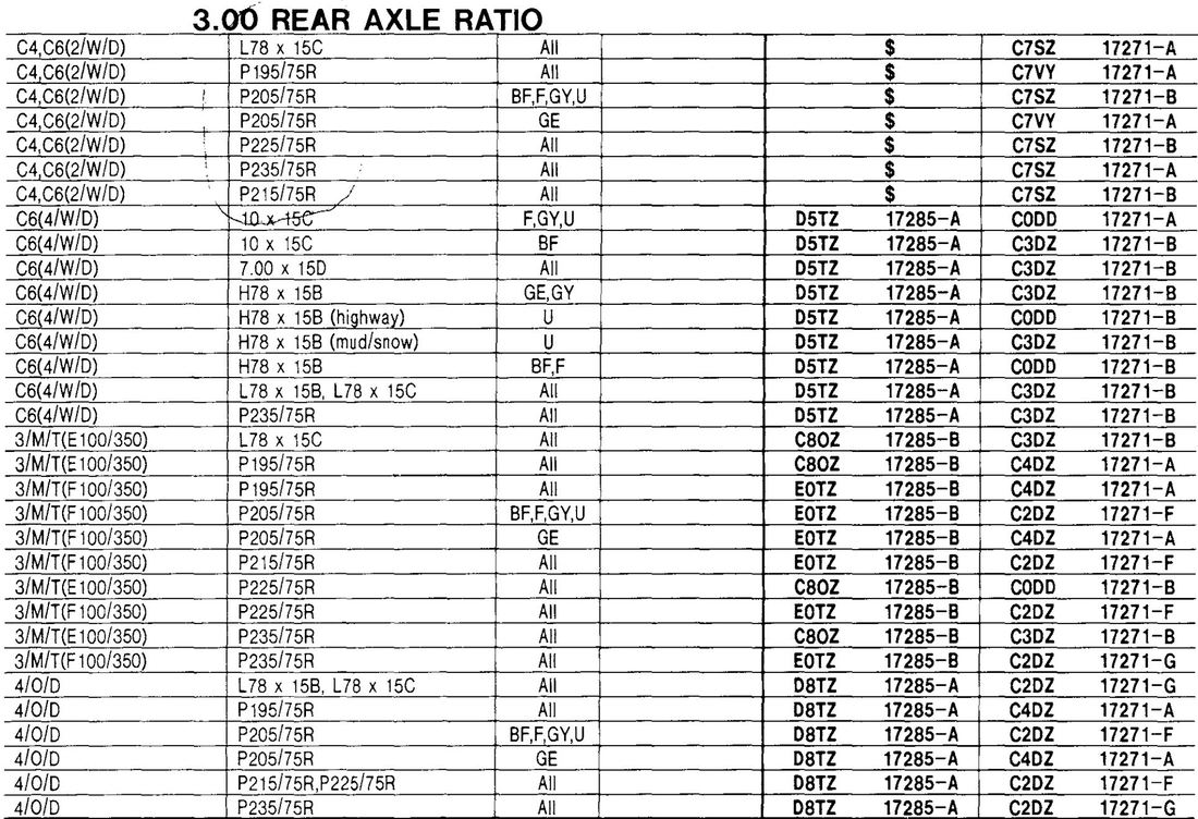
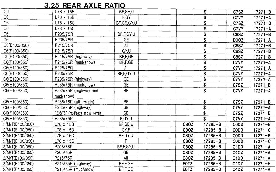
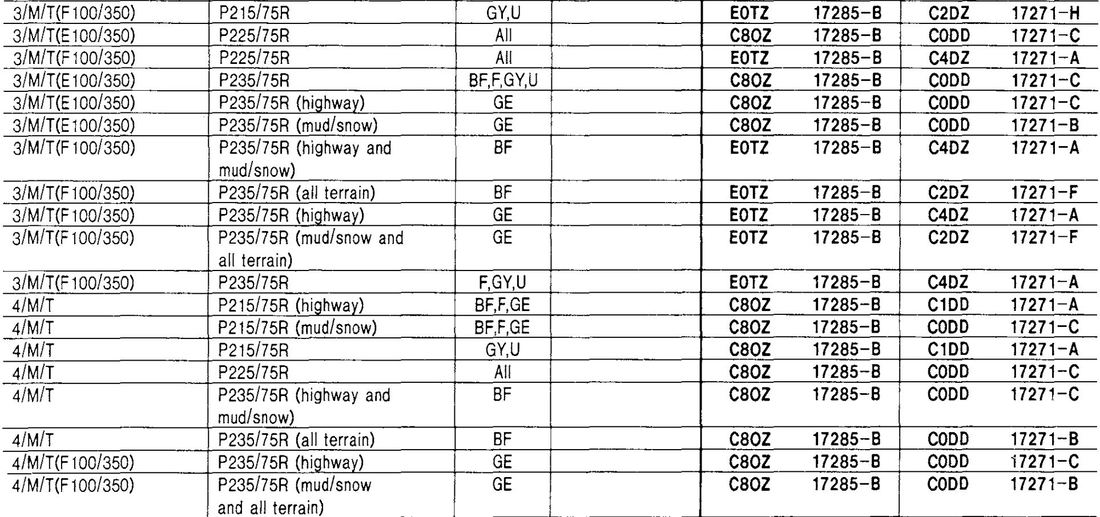
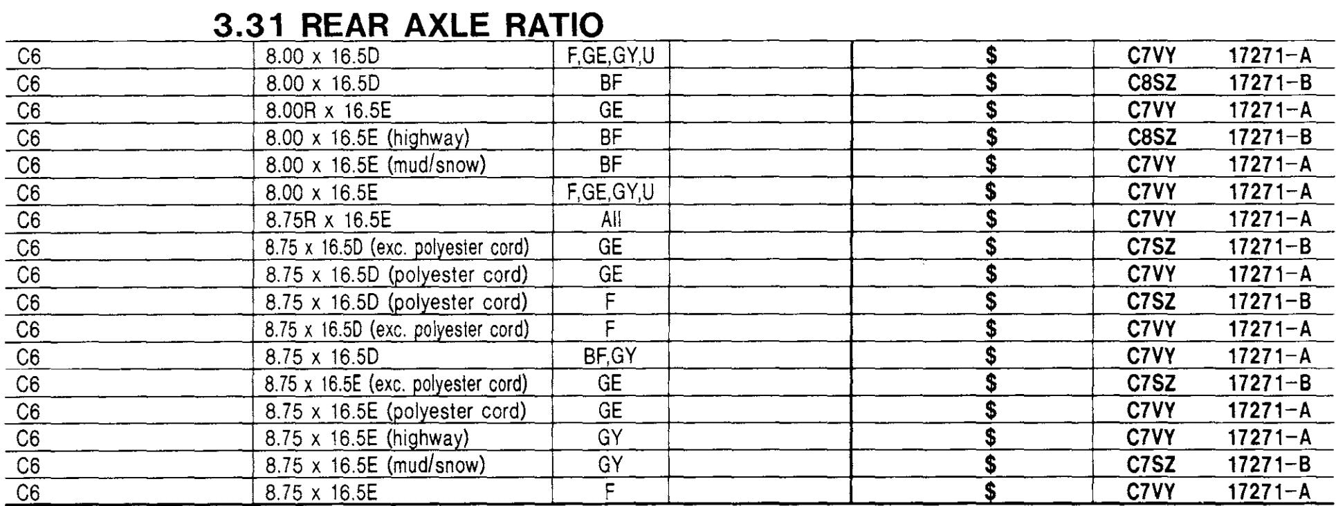
And now to the year-by-year tables. Here you pick your year, transmission or transfer case, and axle ratio to determine the correct drive gear. On the other hand, you could go to the Driven Gear tab and look the drive gear up by gear ratio, transmission, and tire size.
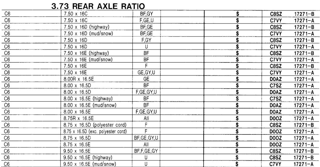
Also, see the note below that says that a "$" in the Drive Gear column means that the gear is actually part of the transmission's output shaft and is, therefore, not replaceable. That was standard on the automatic transmissions.
Also, see the note below that says that a "$" in the Drive Gear column means that the gear is actually part of the transmission's output shaft and is, therefore, not replaceable. That was standard on the automatic transmissions.
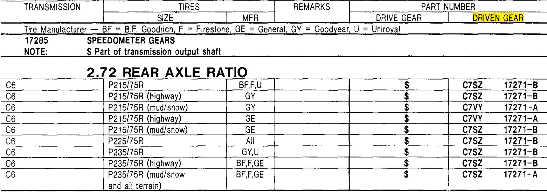
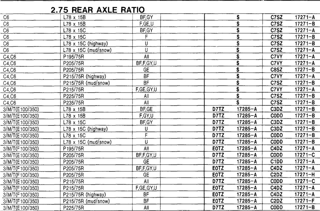
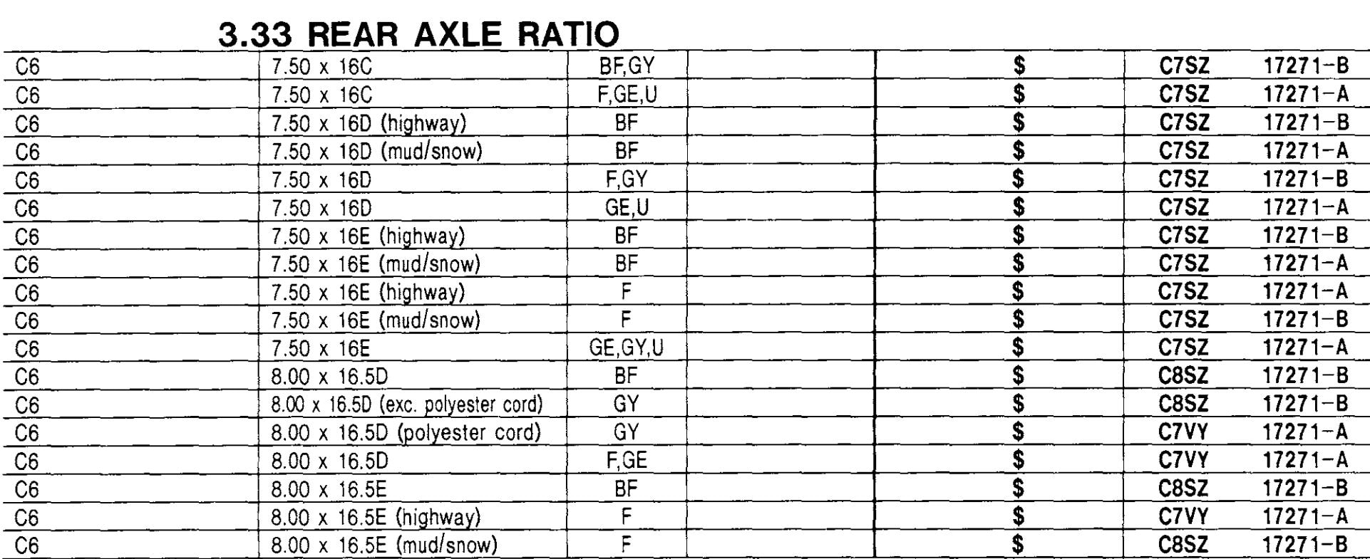
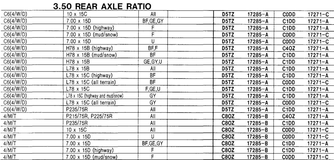
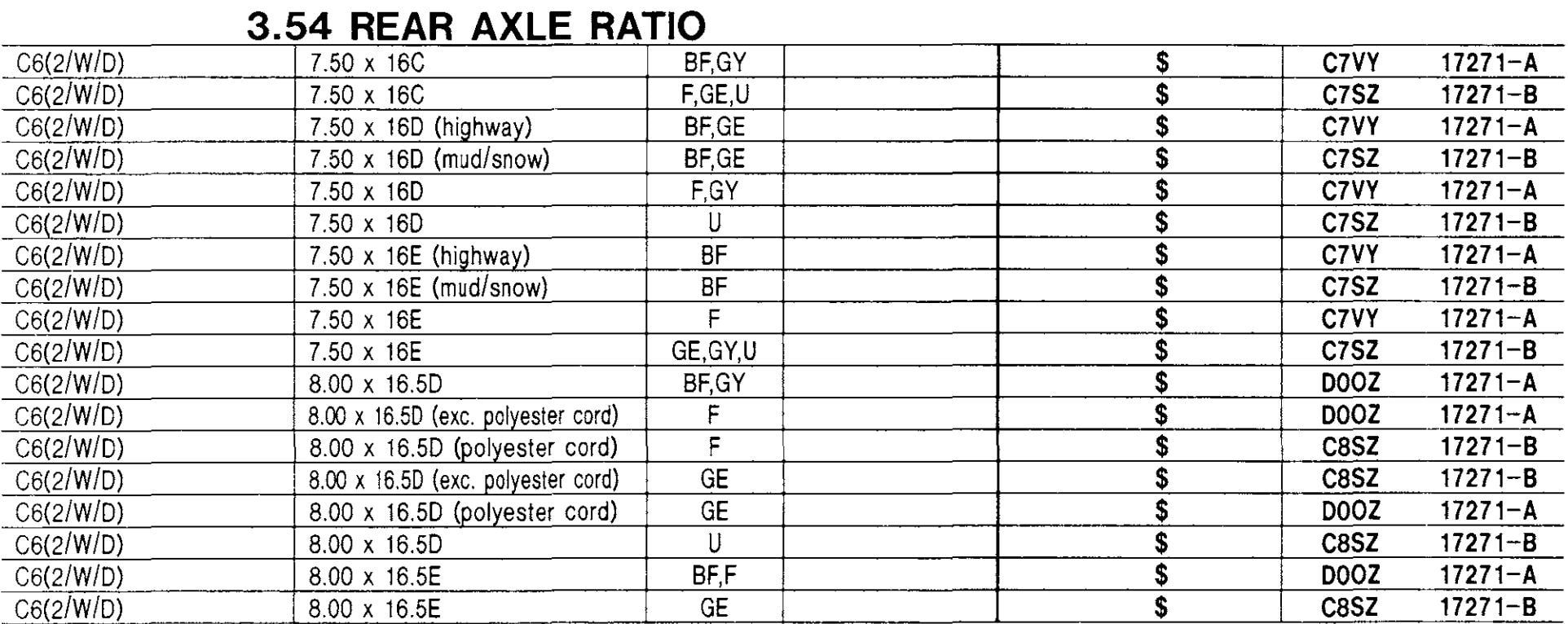
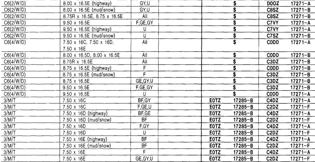
Ok, so now we know what it looks like, and how many teeth and what color each part number is, but what part number do we need? Here are the tables to let you determine that based on your rear axle ratio and tire size. However, while this page was intended for to be for the driven gears, the tables also show the drive gears. Also, the tire sizes listed in these tables are the old-style sizes, so you will have to translate.
The target speedometer shaft speed is 1,000 RPM. The following calculators use that info to let you find the right gear combo to get the speedo reading correctly:
This simple calculation lets you determine what driven gear you need in order to correct an error in the speedometer's readout.
The blue cells are required input, and the green cells are the output:
The blue cells are required input, and the green cells are the output:
- Enter the true speed for this test, usually determined by GPS in the cell currently showing "71"
- Enter the reading your speedometer gives at that true speed in the cell that currently has "75"
- Enter the # of teeth on your current driven gear, the one on the end of your speedometer cable, in the cell that currently has "20"
- The cell that originally had "21" will now show the gear you need in order to get as close as possible to a true MPH reading on the speedometer
- The cell that originally had "71.4" will now show the readout your speedometer will actually have
This calculator is from my friend Steve Hodgson, and it allows you to set up the complete speedometer system, including the drive gear, driven gear, and even an adaptor box if needed.
If you want to do what-if comparisons of two different setups to see which will be most accurate on the speedometer, this calculator is the one to use. Enter the variables in blue and read the output in green.
Before getting into part numbers and lengths for speedometer cables, we should discuss how to remove the cable from the speedometer. It is actually very easy - if you know how.
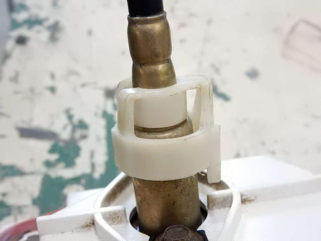
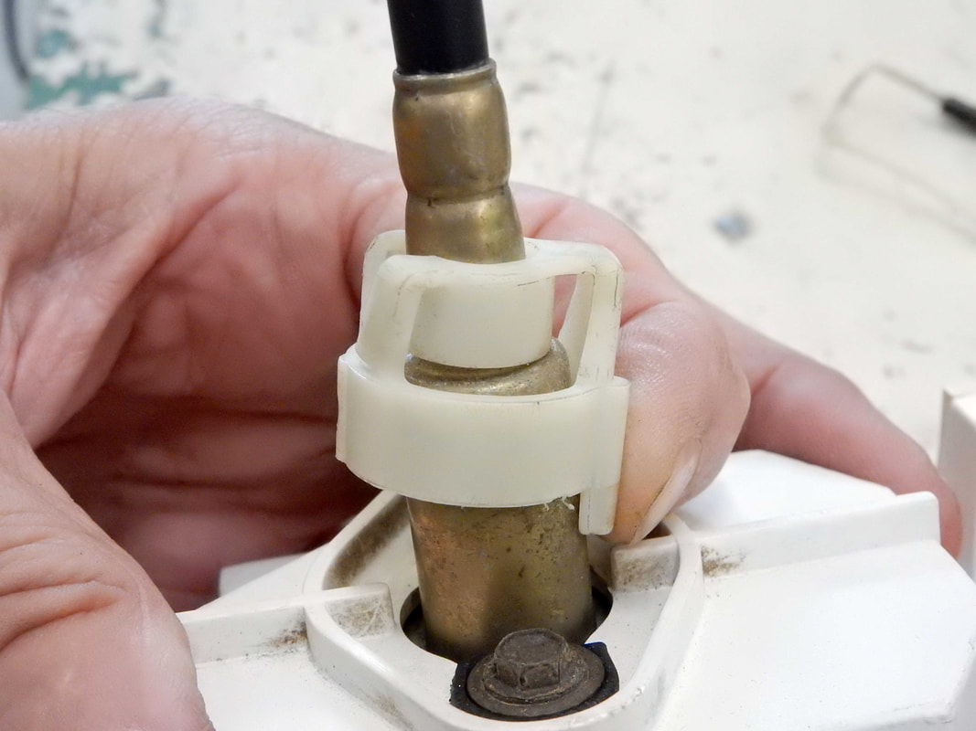
In the picture on the left, below, the cable is locked onto the speedometer. But in the picture on the right the cable is released, just by pushing the tab on the Nylon lock ring. It is that easy. However, you shouldn't be pulling on the cable when you push the tab as the latch may not release. Push on the tab and then gently pull the cable off.
In the picture on the left, below, the cable is locked onto the speedometer. But in the picture on the right the cable is released, just by pushing the tab on the Nylon lock ring. It is that easy. However, you shouldn't be pulling on the cable when you push the tab as the latch may not release. Push on the tab and then gently pull the cable off.
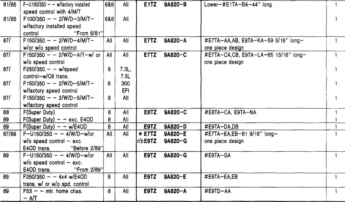
If you decode the info below you'll discover that from 1980 through 1985 the speedo cable used with trucks with speed control consisted of two parts - and upper cable, which is part number E0TZ 9A820-F, and a lower cable which varies by application. But in 1986 that changed to being a one-piece cable.
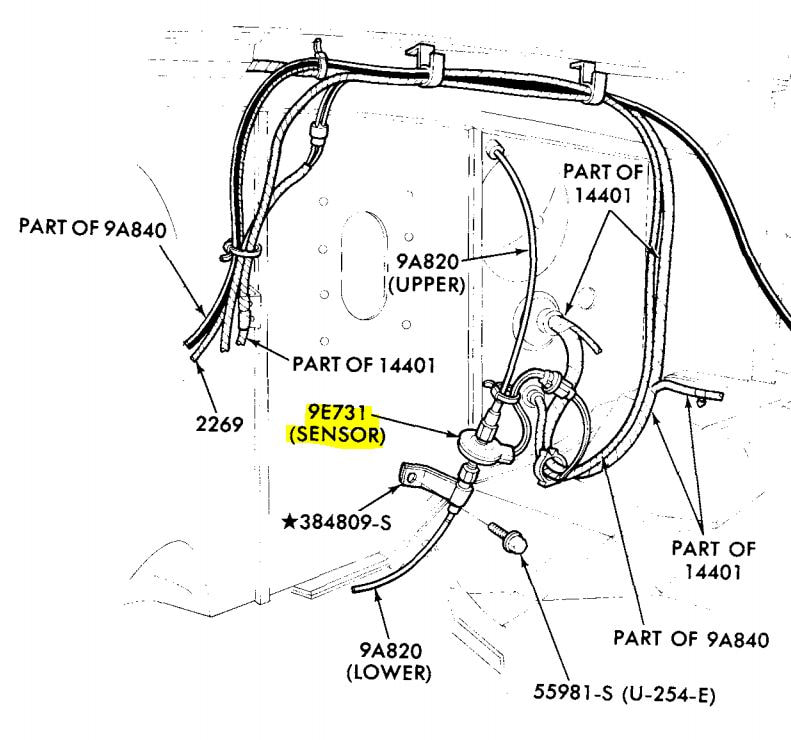
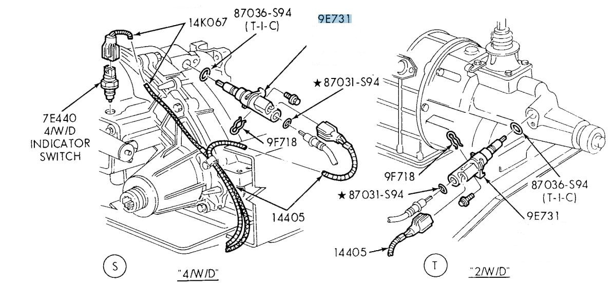
However, if you think about it that can cause some confusion as the two-piece cable was used so they could put a speed sensor in the cable to tell the speed control how fast the truck was going. What happened was that for 1986 the speed sensor was moved to the bottom of the cable and was inserted into the transmission for 2wd vehicles or the transfer case for 4wd vehicles. Click on the Speed Control Sensors tab, above, for more info on them.
However, if you think about it that can cause some confusion as the two-piece cable was used so they could put a speed sensor in the cable to tell the speed control how fast the truck was going. What happened was that for 1986 the speed sensor was moved to the bottom of the cable and was inserted into the transmission for 2wd vehicles or the transfer case for 4wd vehicles. Click on the Speed Control Sensors tab, above, for more info on them.
Trucks with speed control, aka cruise control, had a sensor to determine vehicle speed. From 1980 through 1985 those were in the speedometer cable under the brake master cylinder, as shown on the left, below. But in 1986 they moved to the end of the speedometer cable and were inserted into the transmission for 2wd vehicles or into the transfer case for 4wd vehicles, as shown on the right, below.
The 1980 - 85 speed sensor is part number D4AZ 9E731-B, as shown below, and is Motorcraft DY-145 and is marked D4AF 9E731. Then in 1986 they changed to the sensor that went in the tranny or t-case, which is part number E3AZ 9E731-A and it is Motorcraft DY-382. Then in April of 1989 they introduced a new sensor with part number E9TZ 9E731-A, which replaced the E3 part but still uses the same cable.

